
The ultimate reference for Binson Echorec owners. The AudioExMachina’s Echorec Bible is constantly revised and updated to cover every Echorec model ever produced. To my knowledge this is the only complete catalog of Echorec units available anywhere.
This page is © 2012/2016 by AudioExMachina. Please link to this document instead of duplicating content, thank you.
Table of Content
- 1. Models and Features
- 2. Echorec Models and Pink Floyd: Timeline NEW
- 3. Echorec Models and Pink Floyd: the Adam Ritchie photo sets
- 4. Panel Labels in Various Languages
- 5. Trimpots
- 6. Magnetic Drum
- 7. Magic Eyes
- 8. AC and DC Motors
- 9. Dedicated Preamp Models and Features
- 10. Audio and Foot-Switch Connectors
- 11. Official Echorec Maintenance Instructions NEW
- 12. Echorec, PreMixer and Power Amp: the Binson 7 NEW
- 13. Echorec and PreMixer Integration: the EM6
- 14. Strangest Beasts: Mod. G7
- 15. Strangest Beasts: EC-10 2×10
- 16. Binson and Hagström
- 17. Binson and Guild
- ??? (coming next)
1. Models and Features
| Model | Front Panel | Year | Type | Meter | Heads Play+Rec | Tone Ctrls | Inputs | Selectable Feedback Heads | |
| Binson Echorec : Small Frame Models | |||||||||
 |
Baby Echorec | SilverPlexi | 1960 | Tube | EM81 | 4+1 | 0 | 1 | N |
 |
T3F-A | BlackPlexi | 1960 | Tube | EM81 | 4+1 | 0 | 1 | N |
| Binson Echorec : Large Frame 4-knob Models | |||||||||
 |
B1S | BlackPlexi | 1960 | Tube | EM81 | 4+1 | 0 | 1 | N |
 |
B2 | BlackPlexi | 1965 | Tube | EM81 | 4+1 | 0 | 3 | N |
| T5E (B2) | BlackPlexi | 1965 | Tube | EM81 | 4+1 | 0 | 3 | N | |
 |
B2 Export | BlackPlexi | 1971 | Transistor | EM81 | 4+1 | 0 | 3 | N |
 |
1A (rebranded as Guild) | BlackPlexi | 1965 | Tube | EM81 | 4+1 | 0 | 3 | N |
 |
Echomaster1 (rebranded as SoundCity) | BlackPlexi | 1971 | Transistor | EM81 | 4+1 | 0 | 3 | N |
| Binson Echorec : Large Frame 6-knob Models | |||||||||
 |
Ecorec (note: ECO, not ECHO) | GoldPlexi | 1955 | Tube | EM80 | 4+1 | 0 | 3 | N |
 |
T5E Echorec | GoldPlexi | 1957 | Tube | EM81 | 4+1 | 0 | 3 | N |
 |
T5E Echorec2 | GoldPlexi | 1958 | Tube | EM81 | 4+1 | 1 | 3 | N |
 |
T5E Echorec2 | BlackPlexi | 1960 | Tube | EM81 | 4+1 | 1 | 3 | N |
 |
T6FA | BlackPlexi | 1961 | Tube | EM81 | 4+1 | 1 | 3 | N |
 |
T6FA (rebranded as Guild) | BlackPlexi | 1961 | Tube | EM81 | 4+1 | 1 | 3 | N |
 |
T7E Echorec2 | BlackPlexi | 1962 | Tube | EM81 | 4+1 | 1 | 3 | N |
| |
T7E Echorec2 | BlackPlexi | 1971 | Transistor | EM81 | 4+1 | 1 | 3 | N |
 |
Echomaster2 (rebranded as SoundCity) | BlackPlexi | 1971 | Transistor | EM81 | 4+1 | 1 | 3 | N |
| Binson Echorec : Studio Rack Models | |||||||||
 |
PE-603 | BlackPlexi | 1967 | Tube | EM84 | 4+1 | 2 | 1 | N |
 |
PE-603-T | BlackPlexi | 1969 | Tube | EM84 | 4+1 | 1 | 1 | Y |
 |
PE-603-TU | BlackPlexi | 1969 | Tube | EM84 | 4+1 | 2 | 3 | Y |
 |
PE-603-TE | BlackPlexi | 1969 | Tube | EM84 | 4+1 | 1 | 3 | N |
 |
PE-603 STEREO | BlackPlexi | 1970 | Tube | 2 x EM84 | 2 x (4+1) | 2 x 2 | 2 x 1 | Y |
 |
PE-603-M | BlackPlexi | 1971 | Transistor | EM84 | 4+1 | 1 | 1 | N |
| |
PE-603-T | BlackPlexi | 1971 | Transistor | EM84 | 4+1 | 1 | 1 | Y |
| |
PE-603-TU | BlackPlexi | 1971 | Transistor | EM84 | 4+1 | 2 | 3 | Y |
 |
PE-603-T-6 | BlackPlexi | 1972 | Transistor | EM84 | 6+1 | 1 | 1 | Y |
 |
PE-603-TU-6 | BlackPlexi | 1972 | Transistor | EM84 | 6+1 | 2 | 3 | Y |
| Binson Echorec : Slim Red Head Models | |||||||||
 |
A-601 | RedPlexi | 1969 | Transistor | Mechanical | 4+1 | 1 | 3 | N |
 |
A-601 (rebranded as Guild) | RedPlexi | 1969 | Transistor | Mechanical | 4+1 | 1 | 3 | N |
 |
A-602 | RedPlexi | 1969 | Transistor | Mechanical | 4+1 | 1 | 1 | N |
 |
A-605 | RedPlexi | 1969 | Transistor | Mechanical | 4+1 | 1 | 1 | Y |
 |
A-606 | RedPlexi | 1973 | Transistor | Mechanical | 4+1 | 1 | 3 | Y |
|
A-606 (rebranded as Guild) | RedPlexi | 1973 | Transistor | Mechanical | 4+1 | 1 | 3 | Y |
 |
A-605 TR-6 | RedPlexi | 1973 | Transistor | Mechanical | 6+1 | 1 | 1 | Y |
 |
A-606 TR-6 | RedPlexi | 1972 | Transistor | Mechanical | 6+1 | 1 | 3 | Y |
|
A-606 TR-6 (rebranded as Guild) | RedPlexi | 1972 | Transistor | Mechanical | 6+1 | 1 | 3 | Y |
| Binson Echorec : Desktop Models | |||||||||
 |
EC-3 | Black | 1975 | Transistor | Mechanical | 4+1 | 1 | 3 | Y |
 |
EC-6 | Black | 1975 | Transistor | Mechanical | 6+1 | 1 | 3 | Y |
 |
EC-8 | Black | 1975 | Transistor | Mechanical | 8+1 | 1 | 3 | Y |
 |
EC-10 | Black | 1975 | Transistor | Mechanical | 10+1 | 1 | 3 | Y |
| Binson Echorec : Portable Models | |||||||||
 |
E4T | Black | 1981 | Transistor | LED | 4+1 | 1 | 1 | Y |
| Binson Echorec : Modules in Larger Systems | |||||||||
 |
Binson7 Amp with Echorec | Silver | 1972 | Transistor | Mechanical | 4+1 | 12 | 6 | Y |
 |
EM6 Silver | Silver | 1974 | Transistor | Mechanical | 4+1 | 12 | 6 | Y |
 |
EM6 Black | Black | 1974 | Transistor | Mechanical | 4+1 | 12 | 6 | Y |
 |
ME-8 Mixer with Echorec | Black | 1982 | Transistor | Mechanical | 4+1 | 16 | 8 | Y |
2. Echorec models and Pink Floyd: Timeline
The British band Pink Floyd had Binson Echorec devices as part of their equipment for more than a decade, since their early works up to the 1977 Animals album. This section presents the first accurate study of available visual material (stage/studio photos and videos) with the goal of identifying and catalog Binson Echorec units available on stage during Pink Floyd performances.
Methodology. The devices listed below are included only in those cases where visual proof of presence exists: this means that even when the use of additional Echorec devices may be inferred from acoustic cues, only visible units are listed. Also, due to camera shooting angles, in some performances the Echorec(s) used by a band member may be not visible: even in this case, no inference is made and the device(s) is/are not listed.
During this study, it happened more than once that when some Echorec was reasonably suspected to be present but not visible, the search for extra footage or photos from a different sources/angles, when successful led to discovering additional units.
| Echorec models and Pink Floyd: Legend | |
| Icon | Description |
| |
Echorec Baby. There is a single model. |
| |
Echorec 1. There is a single model. |
| |
Echorec 2 T5E, T6FA or T7E. In general, without a close picture, it’s impossible to tell one model from the others. |
| |
Echorec 2 T6FA. The T6FA for the American market has chicken-head knobs and some minor differences that can be told at some distance. |
| |
Echorec PE 603 series. At least one of the PE603 units has been identified in several different locations/dates as a TU. |
 |
Album related event (such as the first day of the first recording session or the album release day) |
| Echorec models and Pink Floyd: Timeline | ||||
| Date | Location | Event | Notes | |
| |
19661015 | Roundhouse,London,UK | International Times First All Night Rave (launch of the underground newspaper International Times) | First Echorec Baby appearance. First Echorec 1 T5E appearance. |
| |
19661216 | Architectural Association,London,UK | Student Party | |
| |
19661223 | UFO club,London,UK | Opening night | |
| |
19670111/12 | Sound Techniques Studios,London,UK | Recording of Interstellar Overdrive for Tonite Let’s All Make Love In London soundtrack | First Echorec Baby appearance in studio. First Echorec 1 T5E appearance in studio. |
| |
19670127 | UFO club, London, UK | Granada TV documentary, ‘Scene Special’ | |
 |
19670221 | Abbey Road, London,UK | The Piper at the Gates of Dawn recording sessions, first day | |
| |
19670512 | Queen Elizabeth Hall, London, UK | Games for May-Space Age Relaxation For The Climax Of Spring | |
 |
19670705 | Abbey Road, London,UK | A Saucerful of Secrets recording sessions, first day | |
| |
19670805 | The Piper at the Gates of Dawn released | ||
| |
19671021 | De Lane Lea, London, UK | A saucerful of Secrets recording sessions | |
| |
19671217 | Mike Leonard’s House,London, UK | BBC Tomorrow’s World ‘Lights’ documentary | Last Echorec Baby appearance on video. Last Syd Barrett appearance on video as member. |
| |
19680629 | Abbey Road, London,UK | A saucerful of Secrets released | |
 |
19690201 | Pye Recording Studios, Marble Arch, London,UK | More soundtrack recording sessions, first day | |
| |
19690414 | Royal Festival Hall, London, UK | More Furious Madness From the Massed Gadgets Of Auximenes | First Echorec 2 appearance. |
| |
19690613 | More soundtrack released | ||
 |
19690427 | Mothers, Erdington, Birmingham, UK | Ummagumma live recording sessions, first day | |
|
1969 summer | Biggin Hill Airport, UK | Ummagumma read cover photo session | |
| |
19691025 | Ummagumma released | ||
|
19691025 | Mont de l’Enclus,Amougies, Belgium | Actuel Festival | |
 |
19691116 | International Recording Studios, Rome, Italy | Zabriskie Point soundtrack recording sessions, first day | |
 |
19700301 | Abbey Road, London,UK | Atom Heart Mother recording sessions | |
| |
19700329 | Zabriskie Point soundtrack released | ||
|
19700429 | KQED TV Studios, San Francisco, California, USA | An Hour with Pink Floyd (TV show) | |
|
19700516 | The Warehouse, New Orleans, Louisiana, USA | Concert | |
|
19700628 | Kralingse Bos, Rotterdam, Netherlands | The Holland Pop Festival 70 | |
|
19700718 | Hyde Park, London, UK | Blackhills Garden Party | |
|
19700808 | St Tropez, France | St Tropez Music Festival | |
| |
19701002 | Atom Heart Mother released | ||
|
19701204 | Paris, France | ORTF TV show | |
 |
19710104 | Abbey Road, London, UK | Meddle recording sessions, first day | |
|
19710225 | Grosser Saal, Musikhalle, Hamburg, Germany | European tour | |
|
19710515 | Crystal Palace Bowl, London, UK | ||
|
19710615 | Abbaye de Royaumont, Royaumont, France | ||
|
19710619 | Palazzo delle Manifestazioni Artistiche,Brescia, Italy | Concert | PE603 series first appearance. David Gilmour’s dual Echorec stack (PE603+Echorec2) first appearance. |
|
19710620 | Palazzo dello Sport, EUR, Rome, Italy | Concert | |
|
19710701 | Stiftshoff, Ossiach, Austria | Internationale Musikforum Ossiachersee | |
|
19710806 | Hakone, Japan | Hakone Aphrodite Festival | |
| |
19710815 | Randwick Racecourse, Sydney, Australia | Australian tour | One of the Echorec 2 (Roger Waters) is identified as a T6FA with 60% probability |
 |
19710104 | Pompeii, Italy | Live at Pompeii recording sessions | |
| |
19711004 | Pompeii, Italy | Live at Pompeii: live performance | One of the Echorec 2 (Rick Wright) is identified as a T6FA with 90% probability |
| |
19711030 | Meddle released | ||
| |
19711213 | Studio Europa Sonor, Paris, France | Live at Pompeii: studio performance | One of the Echorec 2 (Rick Wright) is identified as a T6FA with 70% probability |
 |
19720223 | Obscured by Clouds recording sessions first day | ||
|
19720304 | Château d’Hérouville, Hérouville, Île-de-France, France | Obscured by Clouds recording sessions | |
|
19720522 | Olympic Stadium, Amsterdam | Concert | |
| |
19720601 | Dark Side of the Moon recording sessions, first day | ||
| |
19720602 | Obscured by Clouds released | ||
|
19720629 | Brighton Dome, Brighton, UK | (Peter Clifton film) | |
| |
19720902 | Edinburgh Film Festival in Scotland | Live at Pompeii released at the Edinburgh Film Festival | |
| |
19730301 | Dark Side of the Moon released | ||
|
19730518 | Earls Court | Earls Court Concert | |
 |
19750106 | Wish You Were Here recording sessions, first day | ||
|
19750705 | Knebworth Park | Knebworth Park Concert | |
| |
19750812 | Wish You Were Here released | ||
 |
19760415 | Britannia Row | Animals recording sessions, first day | |
| |
19770123 | Animals released | Last Pink Floyd album featuring Echorec devices | |
3. Echorec Models and Pink Floyd: the Adam Ritchie Photo Sets
Early evidence of the Pink Floyd using Echorec devices on stage is due to the works of British photographer Adam Ritchie. The year is 1966 and band is composed of Sid Barrett, Roger Waters, Nick Mason e Wright.
Adam’s photos document Pink Floyd gigs at three locations: the concert at the Roundhouse for the launch of the underground newspaper International Times, the student party at the Architectural Association, and the famous friday nights at the UFO club.
Adam recalls: “I was there taking pictures because I had previously shared a flat with Hoppy who started the UFO Club in Tottenham Court Road (and the International Times and the London Free School and the Notting Hill Carnival (with Raunie Laslett)). “
[AExM] “The look of your images is awesome, any detail about the shooting technique?”
[Adam] “I took the pix on a Minolta 35mm SLR without flash because you can’t take pictures of a light show with flash. I probably used Ektachrome X film. All my pictures were taken hand held at about 1/2 to one second exposures because the light levels were pretty low. The ones that are sharp are sharp because someone else was taking a flash picture while my camera was open.”
Adam has been so kind to provide a set of nine previews (three shots for each location) of this very important material, for inclusion in the Echorec Bible. I’d recommend everyone seriously interested in Echorec devices to visit his site at www.adam-ritchie-photography.co.uk for browsing his full catalog. You’ll find other gems there.
Roundhouse,London,UK 1966 Oct 15
 Syd Barret, Echorec Baby, Roger Waters, Echorec 1 (behind Roger) |
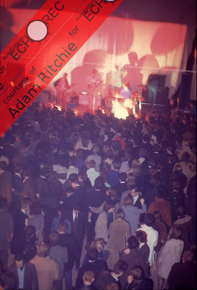 Syd Barret, Echorec Baby, Roger Waters, Echorec 1 (behind Roger) |
 Echorec Baby, Roger Waters, Echorec 1 (behind Roger) |
Architectural Association,London,UK 1966 Dec 16
 Roger Waters, Syd Barrett and Echorec 1 on the floor |
 Roger Waters, Echorec Baby and Syd Barrett |
 Roger Waters, Syd Barrett, Echorec 1 on the floor and Echorec Baby in the background |
UFO club, London, UK 1966 Dec 23
 First gig at the UFO, Syd Barrett playing guitar and Echorec Baby behind him |
 More UFO: Pink Floyd, Echorec1 behind Roger, Echorec Baby behind Syd. Two go-go dancers in the front of the stage |
 UFO: Echorec1, Roger Waters, Echorec Baby, Syd Barrett |
4. Panel Labels in Various Languages
Being a product made in Milan,Italy, for the national market, the language for panel labels on early units was Italian only. With new orders coming also from abroad, and production increasing, French language versions were offered starting with the Echorec1 model. English and German panels followed soon after. Eventually, with the introduction of the Studio Rack line, English became the only language used for every Echorec.
| Labels : Large Frame Echorec1 | ||||
| Functionality | Italian | French | English | German |
| main switch | interruttore spento/acceso/moto | interrupteur eteint/allume/moteur | control off/on/motor | [no german version] |
| mode: echo/bypass/swell | selett. eco-alo eco/normale/alo | selettionneur echo/normal/son | echo swell selector / echo/normal/swell | [no german version] |
| rec level | volume reg. | vol. enregistrement | input control | [no german version] |
| feedback | lungh. alo | longueur de son | length of swell | [no german version] |
| wet level | vol eco-alo | vol. echo-son | volume echo swell | [no german version] |
| delay patterns (heads) | ritardi | retards | echo/swell switch | [no german version] |
| rec level display | livello reg. | niveau enreg. | level indicator | [no german version] |
| I/O channel selector | selettore canali | selectionneur canaux | channel selection | [no german version] |
| Labels : Small Frame and Large Frame 4-Knob Models | ||||
| Functionality | Italian | French | English | German |
| main switch and rec level | vol. reg. / spento | interrupteur / eteint | control / off | schalter / aus |
| feedback | lung. alone / eco | longueur de son / echo | length of swell / echo | schall-lange |
| wet level | vol. alone / ec | volume echo/son | volume echo/swell | lautst echo-schall |
| delay patterns (heads) | ritardi | retards | echo/swell switch | verzögerungen |
| rec level display | livello reg. | niveau enreg. | level indicator | aussteuerungsanzeige |
| Labels : Large Frame 6-Knob Models | ||||
| Functionality | Italian | French | English | German |
| main switch and rec level | volume reg | vol. enregistrement | input control | aussteuerung |
| feedback | lungh. alo | longueur de son | length of swell | schall-lange |
| wet level | vol eco-alo | volume echo/rep/son | volume echo/rep/swell | lautst echo-schall |
| tone | tono bassi/alti | ton bas / aisu | bass/treble | tonelange – tonblende tief/hoch |
| mode: echo/bypass/swell | selett. echo-alo | selett. echo/rep/son | selector echo/rep/swell | wahler echo/wied/schall |
| delay patterns (heads) | ritardi | retards | switch | verzögerungen |
| rec level display | livello reg. | niveau enreg. | level indicator | aussteuerungsanzeige |
| I/O channel selector | selettore canali | selectionneur canaux | channel selection | kanal wahler |
5. Trimpots
Trimpots (miniature potentiometers) are contained in every Echorec model, in order to control several parameters. They are meant to be properly set at the factory, and possibly re-adjusted by technicians as part of the servicing procedures. As a user interface design decision, parameters controlled by trimpots are hidden to the end user by making them adjustable only from the inside of the device.

Echorec2 T5E Trimpots
Trimpots are individually presented below: each one is associated with a short mnemonic, starting with letter “T” (for [T]rimpot).
TD – Dry Level
what: controls the amount of dry input signal that passes-through to the output. The trimpot acts at the output of the first tube/transistor, thus you can either attenuate the input signal or boost it above unity gain, as desired.
when: since the first 1955 Ecorec prototype.
who: every model (excluding the final version of the PE603-T Tube and Transistor, PE603-M Tube and Transistor, PE603-T6, A602-TR, A605-TR).
TF – Feedback Level
what: controls the amount of wet delayed signal coming from the magnetic drum that is re-injected toward the recording head. This trimpot is of paramount importance when tuning the machine for auto-oscillation.
when: since the first 1955 Ecorec prototype.
who: present on every model ever produced.
TM – Magic Eye Sensitivity
what: controls the amount of dry+wet signal that is routed toward the Recording Level Indicator. The indicator is an EM80/EM81 tube for any small-frame or large-frame machines, an EM84 tube for the PE603 rack models, and a mechanical VU meter for later models.
when: introduced with the Echorec2 and Baby2 families and derived models.
who: every model (excluding the Ecorec, Echorec1, Baby).
TSC1,…,TSCn – Shunt caps
what: control each playback head’s high-frequency roll-off. On the Baby, B1s Tube and Transistor, B2, PE603-TE, PE603-M Tube and Transistor, A601-TR, A602-TR there’s a single trimpot for the summed signal coming from all heads. On every other model there’s one tripot dedicated to each individual head, named TSC1,TSC2,TSC3…
when: since the first 1955 Ecorec prototype.
who: present on every model ever produced.
TSW1,…,TSWn – Swell Playback Levels
what: control each head’s playback level ONLY in swell mode. Allow to choose a reverb tail shape (ramp down,
ramp up, etc..). Do not affect echo or repeat modes. There’s one tripot for each individual head, named TSW1,TSW2,TSW3…
when:introduced with the Echorec2
who:every model (excluding the Ecorec, Echorec1, Baby, B1s, B2 Tube and Transistor, PE603-TE, PE603-M Tube and Transistor, A601-TR, A602-TR).
TI – Input Gain
what:controls the input level, before the first tube/transistor. Note that here we refer to the device’s input level, while the dedicated input knob on the front panel adjusts the disk (recording) input level.
when:introduced with the PE603-T final version.
who:every PE603-x models (excluding the PE603-STEREO), every A60x-TR (excluding the A601-TR), every ECx model, EM6, ET4.
TO- Output Gain
what:controls the output level, after the last tube/transistor.
when:introduced with the PE603-T final version.
who:every PE603-x models (excluding the PE603-STEREO and the PE603-M Tube and Transitor), every A60x-TR (excluding the A601-TR, A605-TR6, A606-TR, A606-TR6), every ECx model, EM6,ET4.

Echorec PE603T Trimpots
The amount and function of trimpots installed onboard varies depending on models. A detailed table is presented below. When the amount of trimpots is different from the typical value as described above (eg. a single TSC trimpot instead of one for each head), this amount is displayed as a number.
| Trimpots: Small Frame Models | |||||||
| Model | TD | TF | TM | TSCx | TSWx | TI | TO |
| Baby | + | + | 1 | ||||
| T3F-A Guild | + | + | 1 | ||||
| Trimpots: Large Frame 4-knob Models | |||||||
| Model | TD | TF | TM | TSCx | TSWx | TI | TO |
| B1 | + | + | + | 1 | |||
| B2S | + | + | + | 1 | |||
| B2 Export | + | + | + | 1 | |||
| 1A Guild | + | + | + | 1 | |||
| Echomaster1 TR SoundCity | + | + | + | 1 | |||
| Trimpots: Large Frame 6-knob Models | |||||||
| Model | TD | TF | TM | TSCx | TSWx | TI | TO |
| Ecorec | + | + | + | ||||
| T5E Echorec1 | + | + | + | ||||
| T5E Echorec2 | + | + | + | + | |||
| T6FA | + | + | + | + | |||
| T6FA Guild | + | + | + | + | |||
| T7E Echorec2 | + | + | + | + | |||
| T7E Echorec2 TR | + | + | + | + | |||
| Echomaster2 TR SoundCity | + | + | + | + | |||
| Trimpots: Studio Rack Models | |||||||
| Model | TD | TF | TM | TSCx | TSWx | TI | TO |
| PE 603-T | + | + | + | + | + | + | |
| PE 603-TU | + | + | + | + | + | + | + |
| PE 603-TE | + | + | + | 1 | + | ||
| PE 603-STEREO | 2 | 2 | 2 | 8 | 8 | ||
| PE 603-M | + | + | + | + | |||
| PE 603-M TR | + | + | + | + | |||
| PE 603-T TR | + | + | + | + | + | + | |
| PE 603-TU TR | + | + | + | + | + | + | + |
| PE 603-T6 | + | + | + | + | + | + | |
| PE 603-TU6 | + | + | + | + | + | + | + |
| Trimpots: Slim Red Head Models | |||||||
| Model | TD | TF | TM | TSCx | TSWx | TI | TO |
| A601 TR | + | + | + | + | |||
| A602 TR | + | + | + | + | + | ||
| A605 TR | + | + | + | + | + | + | |
| A606 TR | + | + | + | + | + | + | |
| A605 TR6 | + | + | + | + | + | + | |
| A606 TR6 | + | + | + | + | + | + | |
| Trimpots: Desktop Models | |||||||
| Model | TD | TF | TM | TSCx | TSWx | TI | TO |
| EC3 | + | + | + | + | + | + | |
| EC6 | + | + | + | + | + | + | |
| EC8 | + | + | + | + | + | + | |
| EC10 | + | + | + | + | + | + | |
| Trimpots: Portable Models | |||||||
| Model | TD | TF | TM | TSCx | TSWx | TI | TO |
| E4T | + | + | + | + | + | + | |
6. Magnetic Drum
The magnetic drum, heart of the Echorec’s recording subsystem, is a metal component shaped as two stacked cylinders with a central axle. The lateral surface of the top cylinder is covered by an additional aluminium ring. This ring is an early visual hint about the age of drum assemblies. Early generation rings (for the Ecorec prototypes, the Echorec1, the T5E first generation Echorec2) extend from the border torward the center of the top drum face by 0.5in/1.15cm while later more common models just by 0.2in/0.5cm.
In the rest of this section, when two alternative measures are reported, the former is from early generation drums, the latter from later ones. Figures are provided in two units of measure: inches (in) and centimeters (cm).
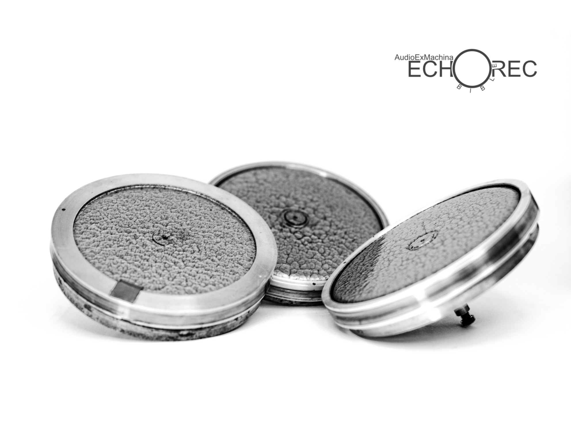
Echorec Magnetic Drums: early generation (left) and later ones.
The top cylinder has a diameter of 4.7in/12cm and is 0.6in/1.45cm to 0.8in/1.95cm tall, depending on version. The aluminium ring surface exhibits a recessed zone, 0.3in/0.8cm wide, fitted by an ultra-thin iron wire accurately wound around. The result is a smooth metallic tape loop that gets magnetically written and read by the recording, playback, erase heads, according to the wire recording principles (the main difference here being the substantially wider audio track substrate on the Echorec, compared to typical wire recorders).
The top flat surface of the drum is decorated with a beautiful psychedelic motif. The effect is obtained by adding 0.4% liquid silicone into the paint mixture. The very last generation of drums, late seventies, exhibit a solid-black finish instead.
The bottom cylinder, smaller, is 4.4in/11.15cm to 4.5in/11.5cm in diameter, and 0.3in/0.8cm tall. The external surface of this component is the end-point of the motion transmission chain whose starting-point is the Echorec electric motor. Early generation drums are much heavier (2.82lbs/1.28kg) as the bottom cilinder is solid-metal. Later models feature an hollow bottom cylinder, the total drum weight being just 0.99lbs/0.45kg.

Echorec Heavy 1959 (left) and Light 1967 (right) Drums
The drum axle extends up to 2in/5cm below the top surface of the drum. Axle’s diameter is 0.3in/0.8cm cm. Near the lower end of the axle (in the pictures the drum is turned upside down and the lower end is the one facing up) there’s a milled zone where the diameter is reduced to 0.2in/0.5cm.

Echorec Drum Shaft
The milled zone at the bottom of the axle is meant to inhibit vertical axial movements of the whole drum assembly by means of a locking screw inserted into a dedicated threaded hole located on the drum shaft sleeve.
Personally I keep all my drums unlocked for easier manteinance and access to internal parts. WARNING: if the unit is moved, an unlocked drum might fall to the ground and be severely damaged. Be careful if you unlock your drums.

Echorec Drum Shaft Sleeve: Threaded Hole for Locking Screw (right).
The magnetic drum is actuated by a rubber wheel, which in turn is actuated by the Echorec electric motor shaft. The wheel freely rotates around a static axle. Friction against the static axle is controlled by a metal ring placed at the center of the rubber wheel.
Rubber wheels of different Echorec models may have different inner metal rings. The difference is in the profile and depth of such rings.
A wrong wheel/axle pair displaces the wheel vertically, resulting in the rubber surface being unable to reach the drum’s bottom cylinder and impacting against the top cilinder (the one devoted to recording). This happens also when mounting an otherwise correct wheel/axle pair with the wheel’s bottom surface incorrectly facing up (reverse mounting).

Echorec Rubber Wheels with Different Inner Rings
The rubber wheel is mounted on a slide that is pushed torward both the motor shaft and the magnetic drum’s bottom cylinder by a spring-loaded mechanism. The wheel is secured on its axle by one of two methods, depending on model: a screw and washer or a metal collar.

Echorec Slide with Screw and Washer on Top (and a Collar in Foreground).
7. Magic Eyes
A magic eye is a special tube whose purpose is to provide visual indication about voltage levels. Electrons leaving the cathode hit a luminescent area inside the tube, called the target. As the amount of voltage applied to the grid (the voltage to be measured) changes, the glowing area of the screen changes in shape accordingly.
In the Echorec the magic eye displays the level (voltage) of the audio signal sent to the recording head for being recorded on disc.
This signal is the mix of the dry input and wet (delayed) feedback. The dry input is controlled by the “input level” knob (and TI trimpot when present). The wet feedback is controlled by the “length of swell” knob (and TF trimpot, always present). The level of the sum of both signals is measured by the magic eye indicator.
The magic eye sensitivity is adjusted by the TM trimpot.
Excluding a limited use of EM80 magic eyes in early units built, the standard luminescent tubes for the Echorec are the EM81 (compatible with the EM80) and the EM84.

EM81 (left) EM84 (right) rear view
The EM81 luminescent screen is an elongated half-oval. Visual feedback is provided by two bright green wings that rotate close to each other as signal level increases. Electrons hit the front face of the screen in order to emit green light.
The EM84 is a micro back-projection device. Electrons hit the back side of a phosphoric strip to obtain green-blue light. Visual feedback is provided by two bars that move close to each other as signal level increases.

EM81 (left) EM84 (right) front view
| Magic Eyes | |||||||
| Tube Model | Year of Introduction | Sensitivity Range | Visual Range | Echorec Models | Datasheets | ||
| EM80 | 1953 | -1V , -14V | 45 degrees (angular) | Prototypes | |||
| EM81 | 1956 | -1V , -10.5V | 60 degrees (angular) | Small Frame and Large Frame (all) | |||
| EM84 | 1957 | 0V , -22V | 21 mm (linear) | Studio Rack (all) | |||
8. AC and DC Motors
Since early prototypes dating mid-50’s, Echorecs have been powered by an AC electric motor. AC electric motors rotate at a fixed speed, proportional to the mains frequency (60Hz in North America, 50Hz in Europe,…). Proper gearing ratio reduces this speed to a value appropriate for the Echorec’s disc (just above one turn per second).
In disc delays, given non-movable heads, disc rotation speed determines delay duration. While other manufacturers of similar mechanical devices experimented variable-ratio gear (e.g. Meazzi), every tube-based Echorec features a fixed gearing ratio (that is, fixed speed and delay durations).
After the development of transistor-based models, Binson introduced versions equipped with a DC electric motor, starting 1971 with the T7E Echorec2 Transistor.
DC motor rotation speed is proportional to supplied DC voltage, rather than frequency, making it easier to possibly implement a variable speed control (the purpose of such a control being to obtain variable delays).
Actually, Binson never released a variable speed Echorec, however retrofitting a DC motor (replacing the original AC motor) and controller into existing AC Echorec models is the standard route followed nowadays by technicians aiming at implementing variable delays as a custom modification.
For the reason explained above Echorec models that come stock with DC motors are especially interesting. After the Echorec 2 TR, more DC models were introduced in the 1971/1973 period, both in the PE603-X and A60X lines. Below is a detailed table.
| Echorecs featuring DC motors | |||||||
| Year of Introduction | Echorec Model | Echorec Type | Notes | ||||
| 1971 | Echorec2 | Transistor only. Tube version fitted with AC motor. | 4 Heads | ||||
| PE603-T | Transistor only. Tube version fitted with AC motor. | 4 Heads | |||||
| PE603-M | Transistor only. Tube version fitted with AC motor. | 4 Heads | |||||
| 1972 | PE603-T6 | Transistor only. Tube version fitted with AC motor. | 6 Heads | ||||
| PE603-TU6 | Transistor only. Tube version fitted with AC motor. | 6 Heads | |||||
| A606TR-6 | Transistor. No tube version. | 6 Heads | |||||
| Binson 7 | Transistor. No tube version. | 4 Heads | |||||
| 1973 | A606TR | Transistor. No tube version. | 4 Heads | ||||
| A605TR-6 | Transistor. No tube version. | 6 Heads | |||||
| A602TR | Transistor. No tube version. | 4 Heads | |||||
A note from John Hamley (Brunswick Amplifier LLC), Echorec servicing specialist in Cleveland, USA:
“Wanted to share an issue that one of the units was having after a rewire by someone else. The unit was brought in with the motor spinning very slowly. Careful listening revealed that the motor was “slipping poles,” that is the magnetic field in the motor was outracing the spindle. You can hear this as a warbling sound and vibration coming from the motor. The reluctance motors in the Binsons (without the start cap) are synchronous motors. With two poles, they should spin at 3600 rpm in the US. 2500 in Europe with 50Hz power. It appears that the Guild branded devices have 120V motors built in. The Euro models are 220V. Wiring the Euro model for 120V results in poor startup and poor speed control. (If it ever gets there) Using the 220V tap for the motor on the power transformer on the Euro models obviously fixes this problem. I cannot recall seeing a difference in the motor. Safer to start with the 125V tap if you are not sure. If the motor does not run well, try the higher voltage tap. This of course assumes that the shaft spins freely by hand and there are no bearing issues.”
9. Dedicated Preamp Models and Features
| Model | Front Panel | Year | Type | Echorec Send Faders | Echorec Send Return Channels | Channel Strip: [B]ass [M]id [T]reble [V]ol [S]end | Input Channels | Power Supply | |
| Dedicated Preamp Models and Features | |||||||||
 |
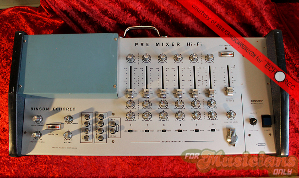
PreMixer HiFi | GoldPlexi | 1959 | Tube | 0 | 3 | B T V | 6 | N |
 |
PA3MN | BlackPlexi | 1961 | Tube | 3 | 1 | B T V S | 3 | N |
 |
PA4MN | BlackPlexi | 1961 | Tube | 4 | 1 | B T V S | 4 | N |
 |
PA6MN | BlackPlexi | 1961 | Tube | 6 | 1 | B T V S | 6 | N |
 |
PA602 | BlackPlexi | 1967 | Tube | 8 | 1 | B T V S | 6+2AUX | Y |
 |
PA602-M | BlackPlexi | 1969 | Tube | 4 | 1 | B T V S | 4 | Y |
| |
PA602-4 | BlackPlexi | 1969 | Tube | 4 | 1 | B T V S | 4 | Y |
 |
PA602-6 | BlackPlexi | 1969 | Tube | 6 | 1 | B T V S | 6 | Y |
 |
PA602-8 | BlackPlexi | 1969 | Tube | 8 | 1 | B T V S | 8 | Y |
 |
PA602-S | BlackPlexi | 1968 | Tube | 8 | 2 | B T V S | 4+4 STEREO | Y |
 |
S600 | BlackPlexi | 1968 | Tube | 2 | 2 | B M T V S + Rvrb + Vbrt | 1+1 STEREO | Y |
 |
A607TR4 | RedPlexi | 1971 | Transistor | 4 | 1 | B T V S | 4 | Y |
| |
A607TR6 | RedPlexi | 1971 | Transistor | 6 | 1 | B T V S | 6 | Y |
| |
A607TR8 | RedPlexi | 1971 | Transistor | 8 | 1 | B T V S | 8 | Y |
10. Audio and Foot-Switch Connectors
While standard TS and TRS connectors are mounted on the Studio Rack and later product lines, several Small-Frame and Large-Frame Echorec models (see table below) feature special audio connectors made by Geloso, an italian electronic components and devices manufacturer.
| Echorec Models with Geloso sockets (models not listed here mount always TS/TRS sockets) | |
| Echorec Model | Notes |
| Echorec Baby | all units have Geloso sockets |
| B1S | early units: Geloso sockets – later units: TS/TRS sockets |
| B2 | early units: Geloso sockets – later units: TS/TRS sockets |
| T5E Echorec | all units have Geloso sockets |
| T5E Echorec2 GoldPlexi | all units have Geloso sockets |
| T5E Echorec2 BlackPlexi | all units have Geloso sockets |
| T6FA | all units have Geloso sockets (Guild versions: TS/TRS sockets) |
| T7E Echorec2 | almost all units have Geloso sockets (some later units: TS/TRS sockets) |
Geloso sockets and plugs are listed as parts N.398 and N.396 in Geloso catalogs. On the Echorec, the N.398 socket is used in audio I/O ports and also in the Premixer port for connecting (if model offers this feature) to the dedicated Premixer PA-3/4/6 MN external preamps.
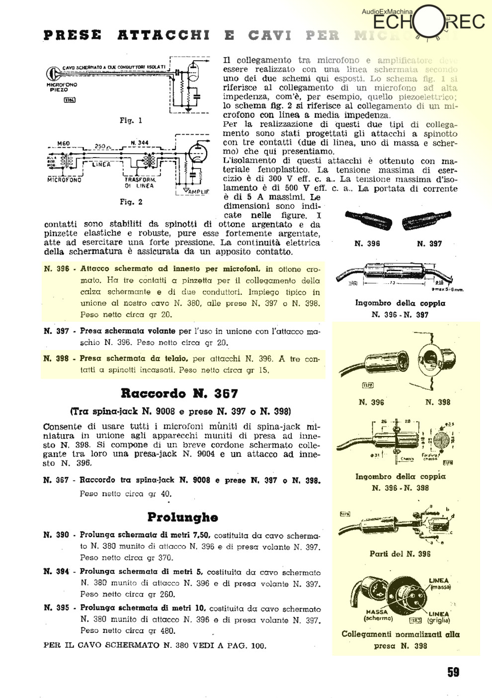
Binson Echorec N.398 and N.396 connectors from Geloso parts catalog
The connector’s three silver-plated pins handle voltages up to 300V RMS. Insulation is granted up to 500V RMS. Max current: 5A. A dent on the plug grants correct pins/holes matching after insertion.
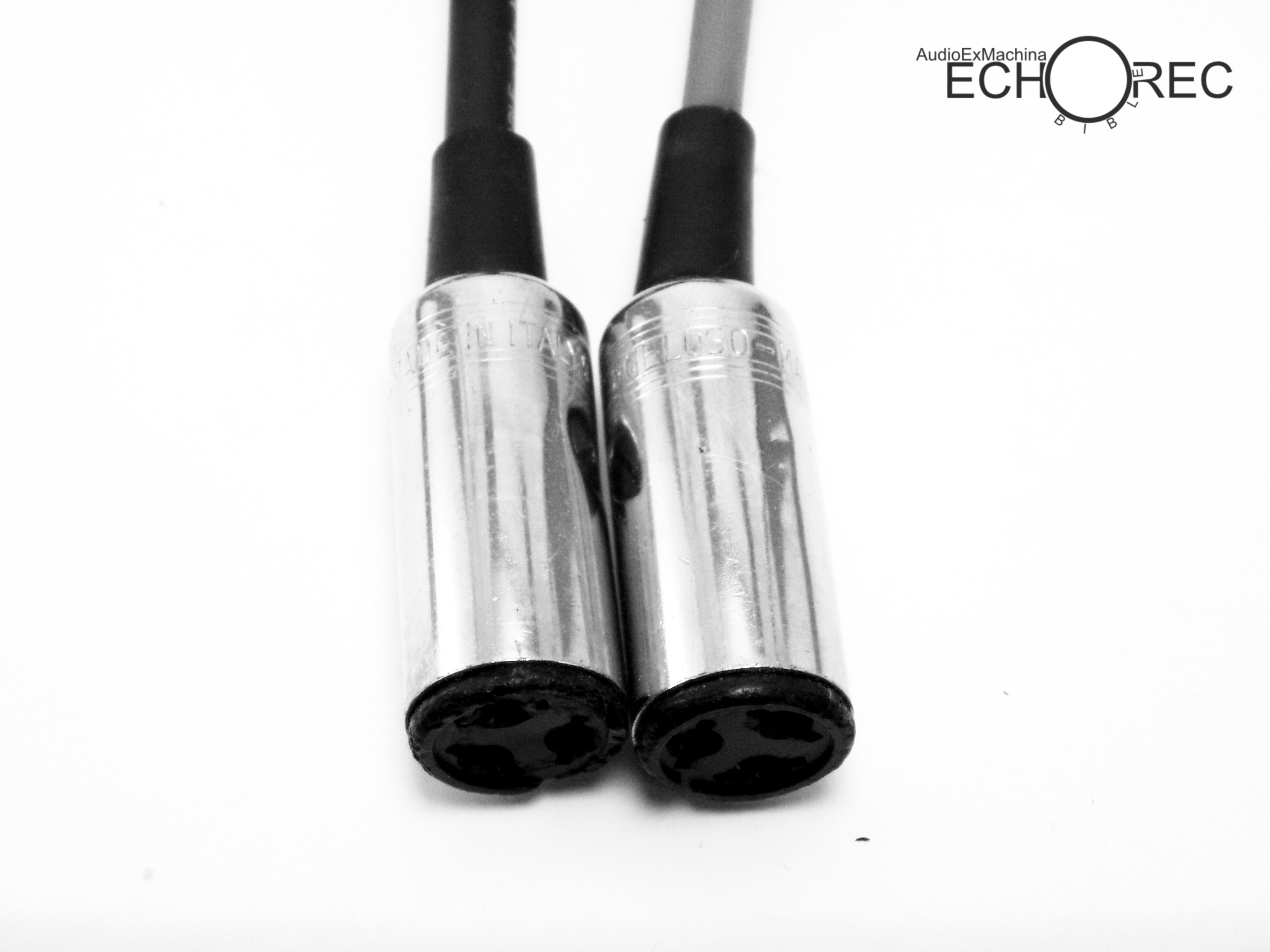
Geloso plugs for the Echorec
While replacing Geloso sockets with functionality equivalent TS sockets is a common restoration/upgrade practice, some owners prefer to preserve the original parts as this results in an higher collectible value. In this cases, adapter cables can be built with a Geloso plug on one side, and a TS female plug on the other one.
On the Echorec, of the three pins in the socket two are grounded and one (the pin diametrically opposite to the dent) carries signals. The adapter is an unbalanced cable that maps a two-contacts TS to the three-pin Geloso scheme.
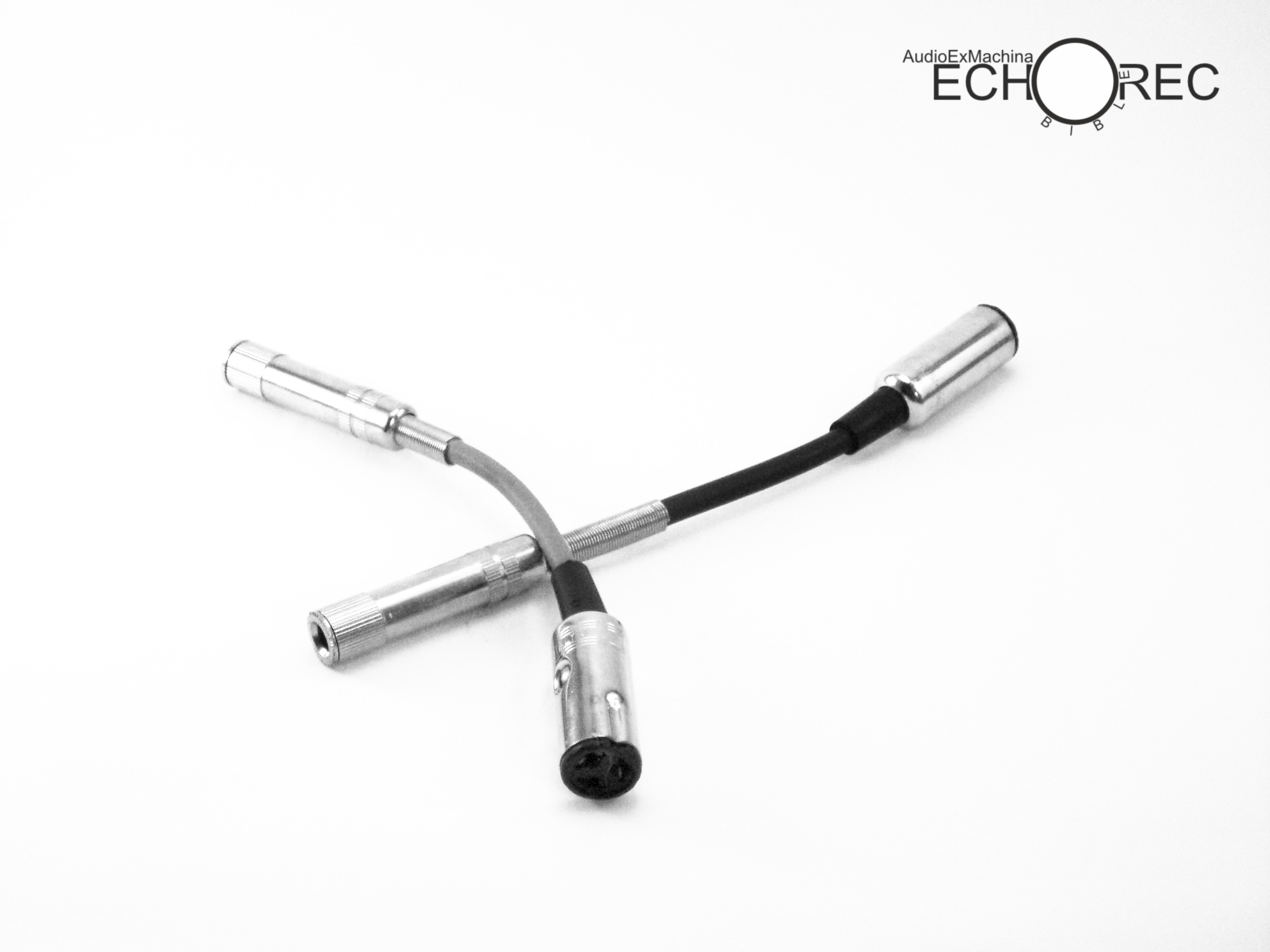
Adapter cables for Echorec models with Geloso sockets. Note the alignment dent on the plug’s surface.
Echorec footswitch sockets and plugs are Geloso parts too. They consist in a jack connector with reduced diameter (5mm) compared to common 6.3mm parts. The 5mm plug and sockets correspond to Geloso parts N.9008 and N.9004.

Binson Echorec – Geloso audio (top) and foot-switch (bottom) connectors
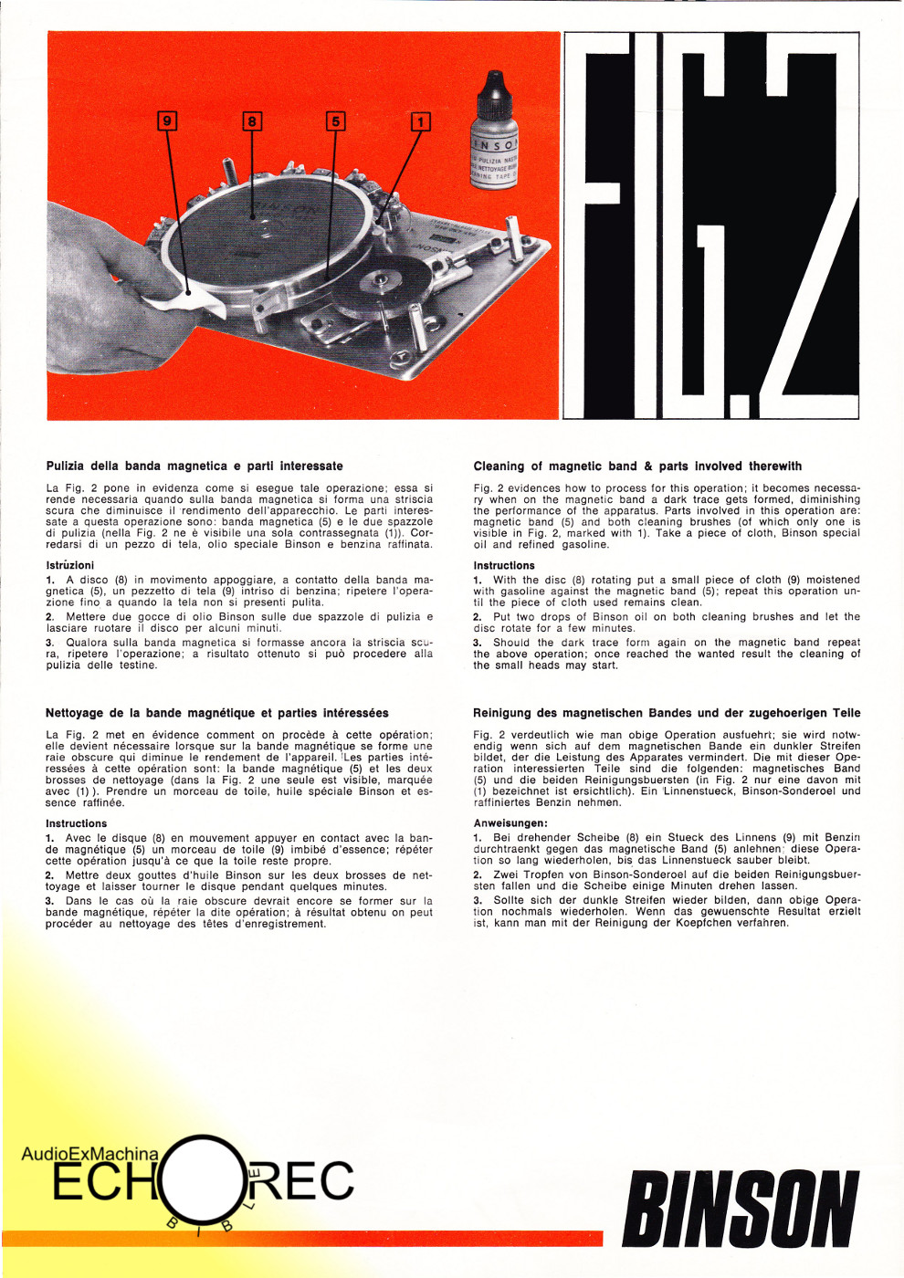
11. Official Echorec Maintenance Instructions
Official maintenance instructions from the original Binson documentation.
 Official Echorec maintenance instructions, pag1. |
 Official Echorec maintenance instructions, pag2. |
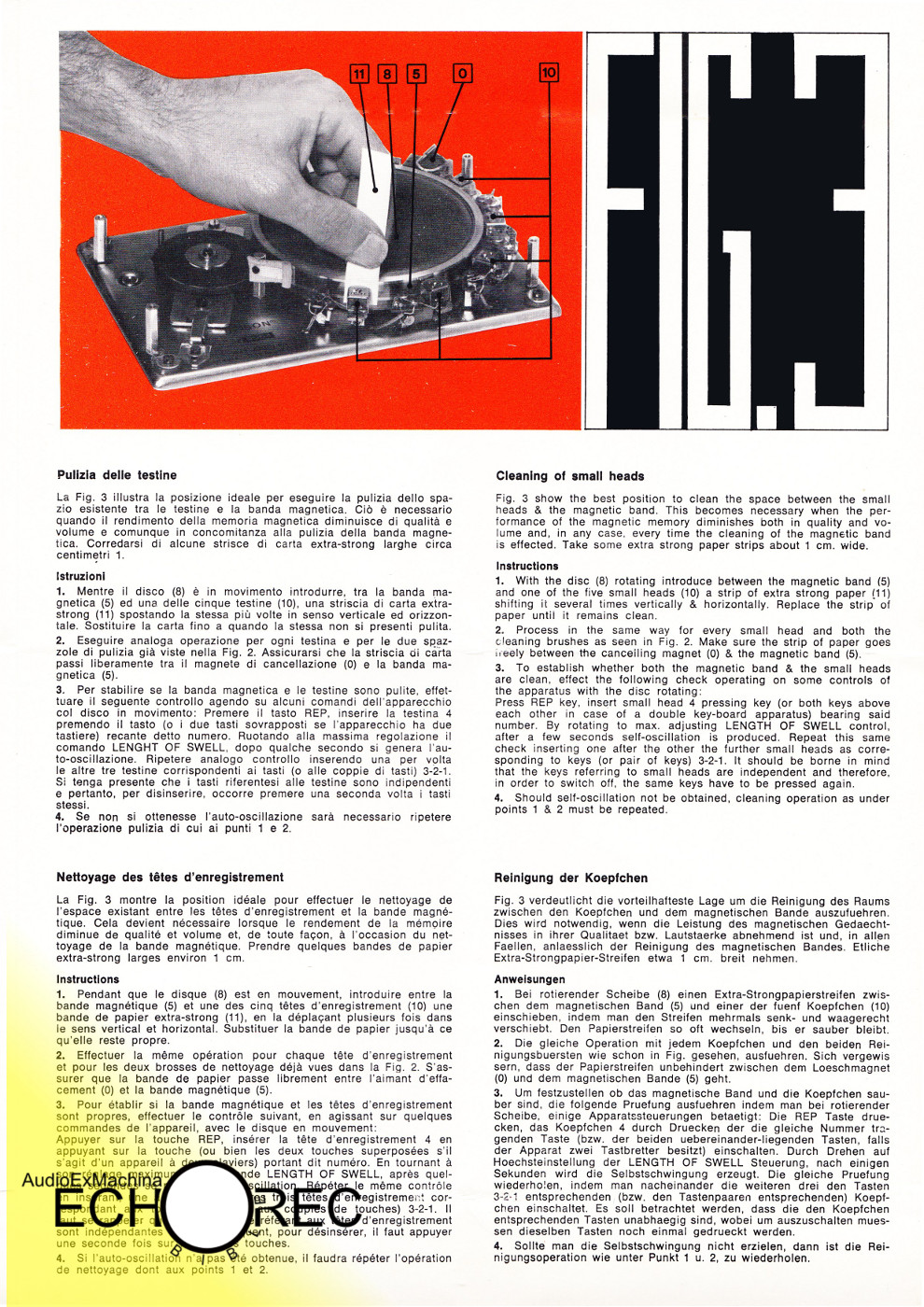 Official Echorec maintenance instructions, pag3. |
12. Echorec, PreMixer and Power Amp: the Binson 7
The Binson 7, also known as Amplificatore 7, is an unique device consisting of a cabinet that houses a PreMixer unit, a power amp and an Echorec. The external shape reminds more a personal computer tower case than a vintage analog musical device. Another easily recognizable feature is its cyan/silver livery, later used also for the 1974 EM6 Echorec.
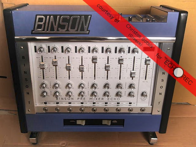 BINSON 7 – front panel. |
 BINSON 7 – rear panel. |
The project dates 1972. Despite being the first step torward the integration of a multi-channel mixer/preamp and an Echorec, the Binson 7 still presents well separated user interfaces for the mixing and echo functionalities. Complete integration will be reached two years later, with the 1974 EM6.
The presence of a power amp section is no surprise as Binson started making tube amps in the early 50’s, before the Echorec was invented. Since 1967, beside tube amps, Binson manufactured also transistor amps.
The Binson 7 is a fully solid-state design, available in two flavours: 100W and 200W. The 100W model drives 1x8ohm speaker cabinet, the 200W 2x8ohm or 4x4ohm cabinets.
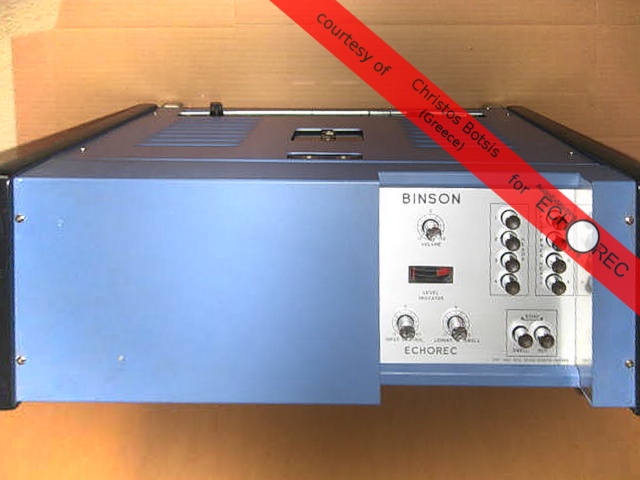 BINSON 7 – top, disc cover. |
 BINSON 7 – top, Echorec controls. |
The mixer section features six or eight channels (depending on versions), each with a switchable input transformer. Each channel strip contains the following controls (from top to bottom): echo level, channel level, treble, bass, input impedence selector.
The input sockets for all channels are on the front panel, excluding an additional AUX input (available on most Binson PreMixer models) on the rear pannel,
 BINSON 7 – top, front. |
 BINSON 7 – top, rear. |
The Echorec section is based on a four-head disc memory module. For each playback head two push buttons allow to send the disc signal to the output bus and/or the echo feedback bus. This set of buttons, known at Binson as the “keyboard”, was used for the first time on the PE603-T (T stands for “Tastiera”, Italian for “keyboard”).
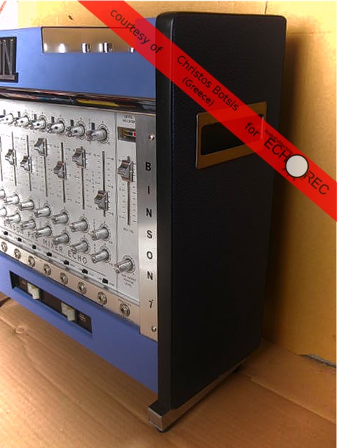 BINSON 7 – side. |
 BINSON 7 – rear. |
The unit is powered by an unusual (compared to the typical AC motor in previous models) DC motor at 9V. Electronics are exclusively solid-state, no tube versions, following the trend started with the A60x (Slim Red Head) series.Also from the A60x comes the mechanical VU meter, however the Binson 7 has a couple of them (Echorec level and mixer level).
13. Echorec and PreMixer Integration: the EM6
The EM6 is a special Echorec model from 1974, the first and only example of full integration between an Echorec memory module and a PreMixer unit. The Binson PreMixer, initially introduced in 1959 and produced up to the 70’s in several different generations, is a multi channel mixer with input transformers and sends dedicated to the Echorec.
See further details about the PreMixer in the PreAmp section.
EM6 – Echorec memory module and PreMixer unit integrated into a single device.
Actually, the Amplificatore 7 (seventh generation of the Binson amp) designed two year earlier already featured several devices mounted on a single chassis ( an Echorec, a PreMixer, a 100W power amp), however these modules were still well separated entities interfaced together.
With the EM6, for the first time a seamless control surface exposes knobs and faders for operating both the Echo and the PreMixer. This unique design won’t be replicated in later products but in the early 80’s Binson resumes the concept by proposing their larger mixing consoles (ME and M12/18/24) with onboard Echorec units.
 EM6 – note the unusual cyan disc cover. |
 EM6 – disc uncovered. |
The EM6 reprises the cyan-silver color schema from the 1972 Amplificatore 7. This unique livery was briefly used for just these two models. Side panels are an unusual electric blue. A cyan-black EM6 was also available.
The following EC series, launched shortly after, shifted to a total black look, with wooden side panels. Cyan won’t be seen anymore in Echorecs.
It’s interesting to note how the extremely rare EC10 2×10 (only one unit is known to exist at the moment), a transitional device from the EM to the EC series, reprises some components and the unusual cyan and electric blue colors from the EM6.
See the EC10 2×10 section for further details.
 EM6 – Echorec controls, details of the “keyboard” on the right. |
 EM6 – closer view of the disc. |
The Echorec EM6 is based on a four-head disc assembly. Each head can be independently selected for feeding the feedback loop by a set of push buttons. This set of buttons, known at Binson as the “keyboard”, was used for the first time on the PE603-T (T stands for “Tastiera”, Italian for “keyboard”).
The unit is powered by the classic Echorec AC motor at 110/220V. Electronics are solid-state only, no tube versions, following the trend started with the A60x (Slim Red Head) series. Also from the A60x comes the mechanical VU meter, however the EM6 has a couple of them (Echorec level and mixer level).
 EM6 – rear panel. |
 EM6 – details of the side panel finish and power switch (both same as in the EC10 2×10). |
The EM6 was proposed by Binson as part of a larger sound system based on PF100 and PF200 power amps.
The unit presented in this section was photographed by Tom Hughes of For Musicians Only, East Haven, CT (USA).
14. Strangest Beasts: Mod. G7
In January 2014 Izy Holvoe from Belgium sent some pictures of a strange Echorec model he acquired years before. Those images were a big surprise: the depicted object was a kind of Binson Echorec I’ve never seen before. Izy anticipated he never found any info anywhere about his device.
What follows below is a technical analysis based on pictures displayed in this section, on additional pictures not published here and on a brief Q & A session with Izy about the state of the device before some reversible modifications he made to convert it to a B2 and about some physical properties of the materials.
Technical analysis: Amplifon Mod. G7
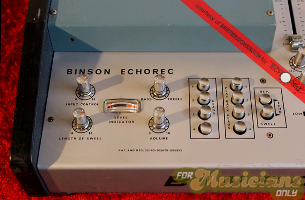
At first sight the device looks obviously like a large frame Echorec. Shape, proportions, size, painting color and method, structure match perfectly those used by Binson for their early series.
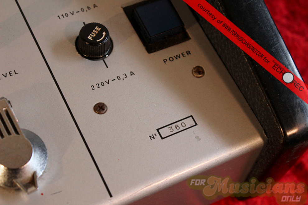
No Binson logo is present on the front panel. The left side plate (displaying the serial number, the Binson logo, the model name) was not mounted or was removed.
NOTE: while there is a single case of Echorecs not featuring the Binson logo (the Sound City rebranded Echomaster1 and 2) every model ever produced displays the Echorec patent number, and this includes the Sound City case were the Echomaster is not explicitly identified as an Echorec.

Mod. G7 – No Echorec-style left-side plate (the mains connector is a modern replacement)
The front panel exposes just two control knobs, unlike large frame models which always feature either four or six knobs. The two knobs are placed in the same position of the two most external knobs on any large frame Echorec. It looks like the remaining knobs were not mounted or removed.
NOTE: Binson proposed the 4-knob series (B1s/B2) as an intermediate line of products placed between the small-frame devices (Echorec Baby/T3F-A) and the large-frame 6-knob ones (Echorec1/2). The 4-knob series was designed as a hybrid solution, featuring the electronics from the small-frame series and the chassis from the large-frame models. Sharing the same chassis, the four knobs on the B1s/B2 are aligned with four of the six knobs of the Echorec1/2 (specifically, their outer pair and the inner pair). The middle pair of knobs, not present on the B1s/B2, corresponds to two empty round holes in their chassis. In the Mod. G7 unit even the inner pair is not mounted.
Analysis of the internal circuitry (pictures not shown here) tells that this is a tube device designed according to the Binson 3+1 tube architecture, as used in the 4-knob large-frame Echorecs. This is either a B1s or a B2.
NOTE: The 4-knob series is based on the 3+1-tube architecture as featured on the Echoerec Baby. 6-knob series is mostly based on the 6+1-tube architecture of the Echorec 2, an evolution of the 4+1 scheme originating from the Echorec 1. The “+1” term refers to the Magic Eye tube.
Despite the lack of a channel selector on the front panel, the right side of the chassis exposes 3 inputs and three outputs. This is a modified B2 (the B1s is single channel).
 Mod. G7 – 3+1 tube architecture from the Echorec B2. See, behind the grid, tube caps on the left, the motor in the middle and the power transformer on the right. |
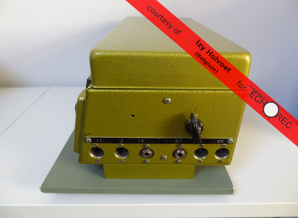 Mod. G7 – 6 I/O connectors, B2-style. The 2 TS connectors are a modern replacement of the original Geloso. The chicken-head knob is a modern upgrade that extends the internal feedback trimpot to the outside. |
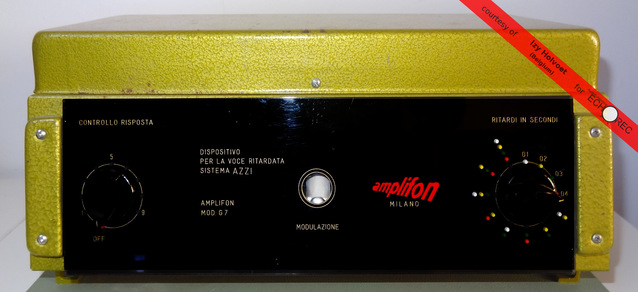
A red logo on the front plexi reads Amplifon. The model name reads: Mod. G7.
Amplifon is an earing aids manufacturer located in Milan, Italy, the hometown of the Echorec. The company was founded in 1950 by Algernon Charles Holland, a former Major in the British Special Forces. While company logo changed over years, the one adopted in the 50’s/60’s is the same depicted in the front panel of the G7. Incidentally, at the time, Amplifon’s head office was less than 3 km. away from the Binson factory.
 |
 |
Text on the front plexi is in Italian. The device is described as “Dispositivo per la voce ritardata”, which translates to “Delayed voice device”. This suggests that instead of being a sound processor, this is rather a speech processor.
Further text reads: “Sistema Azzi” (“Azzi system”). This is the most interesting part.
Dr. Azzo A. Azzi (Hear-nose-throat Clinic – University of Milan – Italy) in the 50’s was involved in research about methods for discovering deafness simulation (malingery). He extended the work of Bernard S. Lee on delayed speech feedback as a cure for voice stutter.
Dr. Azzi invented a test, the delayed speech test, also referred to as the “Azzi test”.
From International Journal of Audiology Jan 1962, Vol. 1, No. 1, Pages 134-144 – Hearing Test in simulation (A.Azzi)
"..The introduction of a time delay in the speech feedback loop with apt electronic devices
 produces a more complex interference in phonation. The test, based on a phenomenon observed
 by LEE, has been developed by Azzi for application in detecting simulation of deafness or
 psychogenic deafness."
From International Journal of Audiology Jan 1962, Vol. 1, No. 2, Pages 191-193 – Malingering Tests (A.Azzi)
"..[delayed speech test"].. It is based on the interference caused by a disturbance brought
 to the ear during speech. This disturbance is the voice of the subject played back to his
 ear with a delay of some tenths of a second.[..] The test is highly reliable[..] It requires
 a special and costly instrument."
Dr. Azzi’s work is also cited in the book “The Ear and the Voice” by french otolaryngologist Alfred A. Tomatis (which, by the way, is a really interesting reading about various aspects of sound and psychoacoustics).
The test prescribes using a delayed signal with a single repetition at a pre-determined level. which means that if an Echorec were to be used as the “special and costly instrument” referenced above, then just the recording level control and the delay selector (the two outer knobs) would be required. The feedback knob and the echo volume knob (the remaining two inner knobs in the B2) wouldn’t be needed.
Is the Mod. G7 the instrument referenced by dr. Azzi in his works? Is this a prototype for later production or was it intented to be one-of-a-kind?
At this point it is not known who manufactured the Mod. G7, whether Binson was directly involved, whether dr. Azzi himself was involved too. The investigation continues.
15. Strangest Beasts: EC-10 2×10
The EC-10 deserves a special mention as it is the Echorec model featuring the largest amount of magnetic heads ever: 10 playback heads, 1 recording head and 1 erase head composed by 3 rare-earth magnets. Independent playback and feedback switches for each head allow to choose among more than one million echo patterns.

Echorec EC-10 Magnetic Drum
The EC line dates 1975 and is composed by the EC-3 (four playback heads), EC-6 (six playback heads), EC-8 (eight playback heads) and the EC-10 (ten playback heads). All models are solid state. While circuits works at 24V voltage, the motor is 110V/220V AC (see the motors section for a detailed list of other solid state series that use 9v DC motors instead).

Echorec EC-10: internal view
Echo patterns are controlled by 10 dedicated push buttons for enabling playback on each head and another set of 10 for enabling each playback head’s feedback to the recording bus/head. You can see them on the right side of the control panel when looking at the official EC10 product picture by Binson. Notice the 4 rows of 5 buttons each.
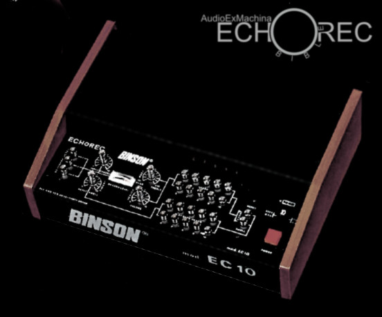
EC-10 Official Binson Picture
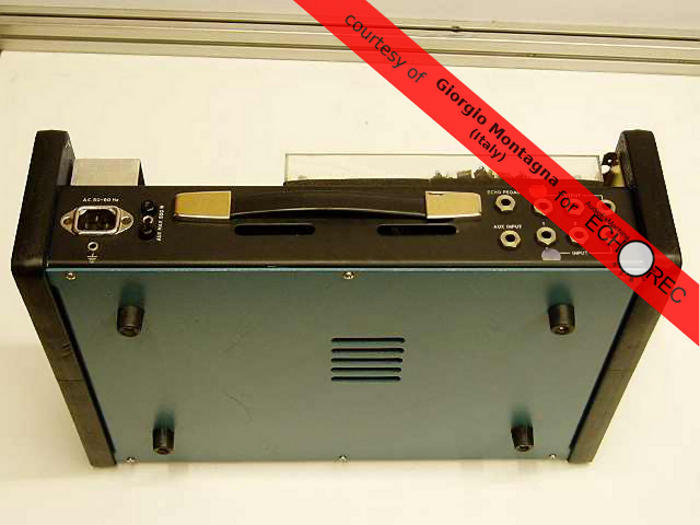
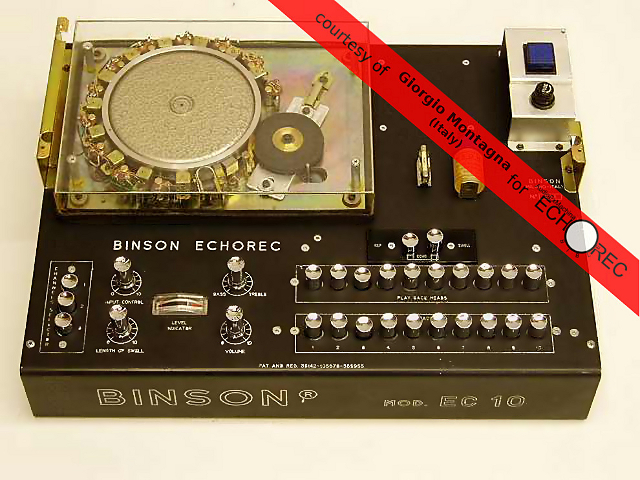
As if the EC-10 weren’t intriguing enough, Giorgio Montagna (Montagna Hi-end Audio Systems, Italy), provided a set of photos depicting an even more interesting EC10 unit. As you can see by comparing Giorgio’s Echorec with the official EC-10 picture by Binson, the control panel layout is different, side panels are different, cover colors (cyan and blue) are different.
 Echorec EC-10 : rare cyan version |
 Echorec EC-10: rare cyan version |
Magnetic head push-buttons are arranged in 2 long rows of 10 elements each. This unusual layout required moving the on/off switch and fuse from the lower panel to the top panel, something that never happened on any EC model.
Echorec EC-10: note the unusual location of the (blue) on/off switch (top right corner)
Side panels, finished in blue, are the same used in the earlier Echorec EM6 model. The cyan metal covers reproduce the livery of the Amplificatore 7 (1972) and the EM6 (1974).
 Echorec EC-10: blue side panels and cyan cover |
 Echorec EC-10: rear view |
It is unclear if this device is a preproduction unit or a custom built one produced later. My opinion is that this is an early EC-10 unit due to the fact that the Binson logo is drawn with an outlined font, as used up to early 70’s, while the EC series always present a Binson logo drawn with a solid, italicized, font, introduced in mid 70’s.
NOTE: The hypothesis is further confirmed by an analysis of images of an early EC-8 unit. Pictures tell us that the EC-8 too was initially introduced with the older Binson logo and a layout consisting of 2 long rows of 8 elements each (stock Ec8 models have 4 rows of 4 elements). In this case however, side panels are brownish and no cyan part is present suggesting that this EC-8 was close to the final design used for the EC series up to the 1980.
This EC-10 is tentatively dubbed EC-10 2×10 to distinguish it from the less rare EC-10 4×5. At present only one 2×10 Echorec unit is known to exist, this one.
NOTE: the EC-8 as well should be considered available in two forms: EC-8 2×8 (old logo) and EC-8 4×4 (new logo).
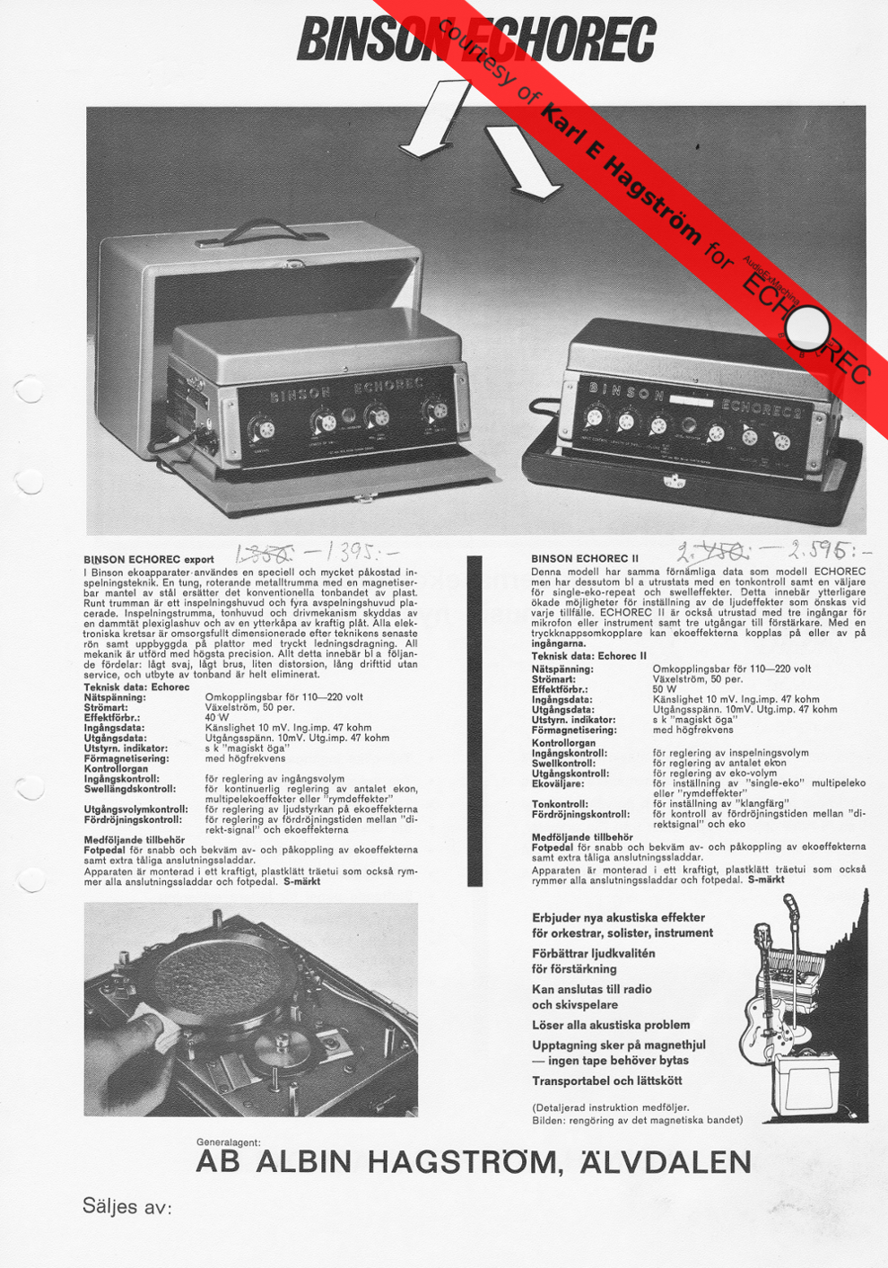
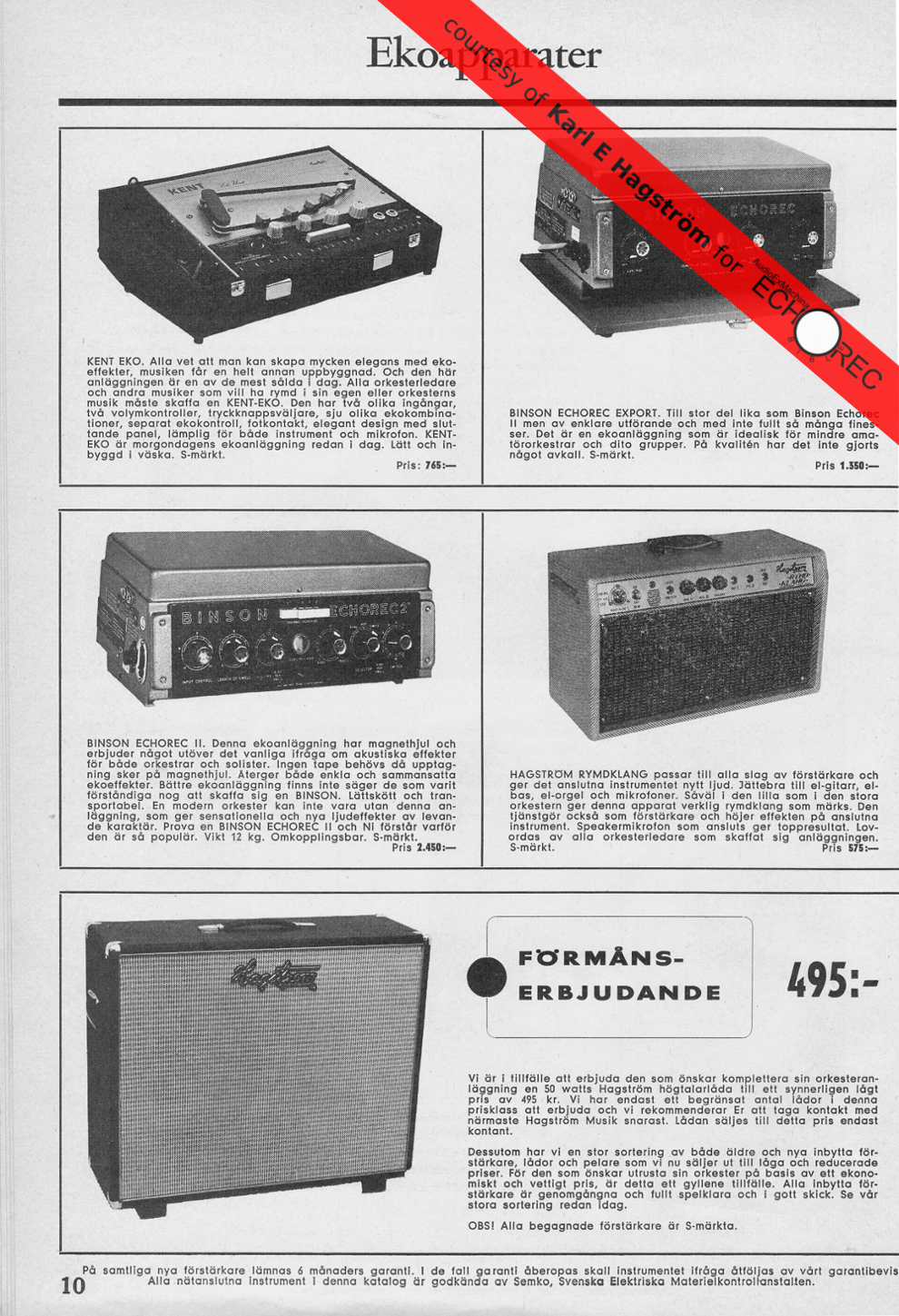
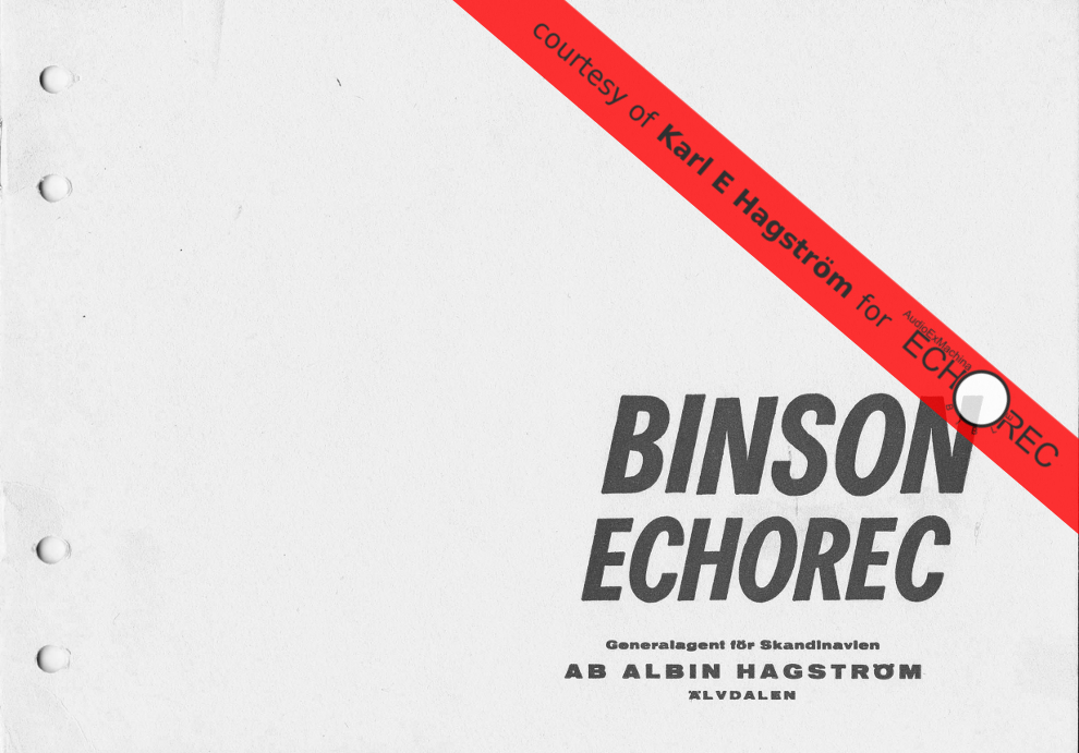
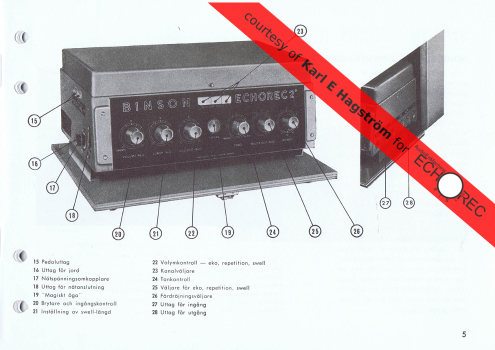
16. Binson and Hagström
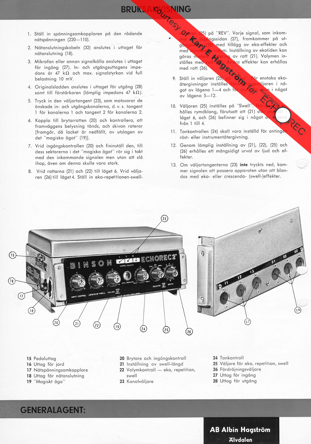
Hagström, famous instrument and amp manufacturer from Älvdalen, Sweden, became the official Echorec distributor for Scandinavia in late 50′s.
Karl-Erik Hagström jr (from HagstromParts.se), grandson of the founder Albin Hagström, kindly provided the Echorec Bible with high resolution scans of brochures, magazine ads and manuals from the 60′s. This is a beautiful gallery of rare images, never seen before on the net. Thank you Karl.
 |
 |
 |
 |
 |
 |
 |
 |
 |
 |
Thanks to Janne Olofsson-Godman (from hagstrom-vintage-guitars.se) for additional help with Hagstrom-related researches.
17. Binson and Guild
Guild, the american guitar manufacturer founded in 50’s, started distributing Echorecs in USA in mid 60’s. The agreement between Binson and Guild stipulated that Echorecs shipped from Italy for the North American market would be rebranded as Guild Echorec by Binson.
Below is a page from the 1966 Guild catalog depicting two tube models presented as Model1 and Model2. Observant readers will recognize them as the small frame T3F-A and the large frame T6F-A. Interestingly the pictures were displaying pre-production models as the knobs are the same typical kind used on Binson Echorecs. Guild Echorecs are always equipped with generic black chicken-head knobs, with no Binson logo.

Guild Echorec by Binson: Model1 and Model2 ( T3F-A and T6F-A)
The partnership continued in the early 70’s, with more models available, namely the A60x red-head series. These units were solid-state only, and the rebranding scheme changed to Binson Echorec by Guild. The PE-603 studio rack series, developed in the same period, were never released with the Guild logo. A60x flyers below.
 Guild Echorec by Binson: A-606-TR-6 |
 Guild Echorec by Binson: A-606-TR and A-601-TR |


June 24th, 2012 at 5:40 pm
[…] The AudioExMachina’s Echorec Bible […]
June 16th, 2015 at 10:50 am
Salve Luigi…
può essere piu preciso sul filo usato attorno al tamburo??? materiale e spessore ? una volta riavvolto il tutto deve essere tornito per “appiattire la superficie”? ce un solo “strato di filo” ? Grazie in anticipo
June 17th, 2015 at 12:08 am
Hi Davide and welcome. Luigi kindly provides links to this Echorec Bible site from his Ebay pages however we are two different persons, I’m not Luigi 🙂
The material wound around the drum is stainless steel wire. Diameter is 0.1 millimeters. Yes, there’s a single layer of wire around the drum.
I wouldn’t recommend trying to sand the wound wire as its diameter is so thin that you’d need an high degree of control over the process. In any case I do re-wind drums and they work fine without any further sanding.
September 2nd, 2013 at 9:37 pm
My hobby is researching the early tape disk echos.I just loved your history on the Binson.
October 10th, 2013 at 6:36 pm
Thank you for visiting.
October 9th, 2013 at 5:40 pm
I have a newly aquired Echorec 2 T7E. It seems it is stuck in bypass mode since I have no footswitch 😦
does any one 1) know the input jack size of the on off footswitch (it’s not 1/4″) 2) can the unit be manually toggled out of “bypass” 3) is there any switches in the modern area that can be substuted.
Thanks Echoless Pete
October 10th, 2013 at 6:54 pm
Welcome onboard Peter, congratulations for your terrific purchase.
Please check out the Audio and Foot-Switch Connectors section of Echorec Bible: the footswitch jack, Geloso part N. 9008, measures 5mm in diameter. For some reason, you’ll find this component listed sometimes as Wandre plug for the Echorec (BTW: Wandre was an artist/artisan (Antonio Pioli) who built very interesting guitars).
The only way to toggle the unit IN bypass is disengaging the button (in the channel selector) corresponding to your input connector (1,2 or 3). It’s virtually impossible to have the unit stuck in bypass if you don’t have a footswitch pedal plugged in. The problem is likely elsewhere, I’d recommend to have the T7E serviced and calibrated if you can’t do it by yourself, you won’t regret it.
October 9th, 2013 at 5:48 pm
also with fingers crossed do you know of anyone in the US qualified to service, restore my gem T7E? I live in Chicago
Long live the Echorec!!!! 🙂
Pete
October 10th, 2013 at 7:05 pm
Sometimes crossing fingers helps …. the Echorec specialist in my lists that’s closest to you is:
John Hamley
Brunswick Amplifier LLC
PO Box 222
Brunswick, Ohio 44212
216-704-0122
http://www.brunswickamplifier.com
October 10th, 2013 at 7:19 pm
Thanks on all fronts!!! Got to get to work on making this echorec sing again.
Shine On
Pete T
October 10th, 2013 at 7:28 pm
Thanks on all fronts….I will let you know how it turns out. A clean unit just needs some TLC.
Shine On.
Pete T.
November 9th, 2013 at 1:37 pm
Howdy Peter. I have a Binson echorette Baby which I need a Circuit diagram for. It has stopped working, motor still rotates but EM81 not lit and only slight glimmer from the rest of valves. On dismantling a short white wire broke off completely and a green wire has also become detached. Wiring so old, so no no surprise there but need circuit to ascertain wiring connections! Willing to pay if copy can be supplied. Many thanks.
Mike
November 12th, 2013 at 10:59 pm
http://pages.ebay.com/link/?nav=item.view&id=301013021996
Try this…..Luigi is the best source of spare parts. Totally reliable. I can’t fix stuff but I know his cd listed on ebay may have what you need. Ask him questions.
I am in the market for a vintage Lorenz motor for a T7E if anyone has one. Please let me know if this helps and the result. Shine On and let’s make this site even better with good info and resources for all. I love that it exists.
Pete
December 12th, 2013 at 9:00 pm
A Binson motor is currently on sale (Ebay) at Luigi’s!
December 10th, 2013 at 12:50 am
DEAR BINSONATICS,
I recently was given an all tube PE 603 in a rather sorry state, due to the moisty
basement it was stored in for 20 years minimum and the wire-rot that apparantly
is an all too common disease with these machines. The disc is in good shape though,
The tape-heads are all out of place , so if anyone has any info on the placement
and how to allign them,….. welcome! The choke is as good as deceased and I would like
to know what value it should have and / or what to replace it with. I am about halfway rewiring
it and it looks more promising with every step, best project of the year!
OK
December 12th, 2013 at 9:13 pm
Hello and welcome! If you have a link to a picture of the disc/heads area then you might get some specific help. In general, if you looked at the disc from the top, you’d see (counter-clockwise): the rec head, then the four playback heads. Heads 1 and 2 go to tube number 2 while 3 and 4 to tube number 1. To number tubes, start with right-most one when looking at the PE603 from the back side. Also, a common color scheme on the PE603 (not necessarily replicated on your machine) for the head cables is: green (rec), orange (play-1), yellow (play-2), white (play-3), red (play-4).
October 25th, 2015 at 1:43 am
I am very interested in the values of the choke. What should I get for a 603 T tube version?
December 12th, 2013 at 8:54 pm
Keep an eye on ebay for Luigi’s spare parts. They are of the highest quality. I am about to send my T7E to Ohio for a look over and head alignment. Shine On
December 14th, 2013 at 6:17 pm
I have a T5E for sale.. Anyone interested?
December 28th, 2013 at 11:33 pm
Hi Audioexmachina, Do you have any photos of the D.C. motors as used in the P.E. 603T? neil
January 8th, 2014 at 8:57 pm
Hi Neil, you say DC motors… my 603’s are all tubes so AC only here, however if you search the vintageamps.com forums there’s a thread about restoring a transistor 603 unit with pictures of the DC motor. Look for the “Binson PE603-T, improvement of the solid state version” thread.
January 30th, 2014 at 1:18 am
Thanks to Audioexmachina for the referral to the top technical Echorec service engineer in the Midwest – and if not the USA. When all routes to the proper person for the job got nowhere, I took the advice here and sent my vintage Binson T7E to Cleveland, Ohio for reconditioning. Let me say I am speechless with the results (see above):
“Sometimes crossing fingers helps …. the Echorec specialist in my lists that’s closest to you is:”
John Hamley
Brunswick Amplifier LLC
PO Box 222
Brunswick, Ohio 44212
216-704-0122
http://www.brunswickamplifier.com
Jedi master John Hamley brought an echoless T7E in ultra-mint condition back to life. I would certainly send any unit to him, as he knows the design, and can do wonders from simple calibration to full rewire and rebuild.
This is what you get: a full assessment of your Binson’s condition from the dials to the motor, a full diagnosis of what needs to be done, a complete explanation of costs up front, and a thorough examination of your Binson to the schematics of the original product.
Once this is done John does his magic from his state of the art workshop. John knows Binson, I originally sent mine to a highly regarded shop in Chicago, but they had no experience and couldn’t tackle the job. John is an ELECTRICAL ENGINEER and can bring the Binson Echorec back to it’s full glory. He is fairly priced and cares for his customers, from receipt of the unit until weeks after follow up. Why? Because he knows what he’s doing and he loves his work. In fact he will go over all repairs remotely via video conference on Skype with your unit – you can talk about everything relating to the project.
All John asks is CAREFUL packaging for the outbound and inbound trips. Our dear Binsons don’t like travel and need a safe journey – so take care in your packaging for shipment. **So my T7E was one of the “mystery” supposed PF Echorecs that appeared in the last 6 years or so. We will never know if it’s was real, but it is a vintage piece of gear that now sings in the full glory of our beloved drum echo. Cheers John Hamley and everyone who reads this awesome website, what a great resource!
Shine On!
Pete T.
Chicago
January 30th, 2014 at 6:03 pm
Pete, I’m copying here a comment from John Hamley just posted in the home page:
Thanks Pete very much. It was a pleasure to work with you and on your Echorec. I have to admit to being a little in awe of the machine if in fact it was truly the property of PF at some time in its life. Every Echorec is worth repairing, and having worked on many tape units as well now, Binson got it right with the magnetic drum. As I get time, I am hoping to work with a local machine shop to see if we can figure out a way to rewind the drums. That is the one service I cannot perform. Each unit that comes in brings its own challenges and I learn more with each repair.
Keep up the cleaning and oiling!
One last thing, the PO Box changed to “222″ :o)
Shine on
John Hamley
January 30th, 2014 at 6:16 pm
Cool, you can change the PO box to the correct 222 in my comments if you wish!
What a great site.
Regards,
Pete
Sent from my Verizon Wireless 4G LTE smartphone
January 30th, 2014 at 6:25 pm
Done, every occurrence of the older PoBox has been replaced.
January 31st, 2014 at 1:31 pm
Hello,
I have some photographs of the echo Binson EC10.
If you communicate to me a e-mail I send you.
Giorgio Montagna- North Italy
January 31st, 2014 at 8:48 pm
Giorgio, the mighty Echorec EC10 with a ton of magnetic heads is a true monster! Congratulations, e-mail message sent.
January 31st, 2014 at 11:31 pm
Extremely useful page, I am listing a Sound city Echomaster 1, On Ebay uk 2nd February 2014 it is the large frame 4 knob, transistor model, i will add a link to your page on my listing (assuming it’s ok with you) The info on your page will help me list my model correctly, Thanks
February 1st, 2014 at 6:19 pm
Yes, please, add a link. Also, if you or the new owner need further advice just leave a note here.
March 4th, 2014 at 12:50 pm
Some photos are very tiny..the link when clicking on the tumbnail should show the full blown picture.
March 4th, 2014 at 5:52 pm
Thanks for your comment and welcome. Only the thumbs in the Model Listing section are tiny as they are ment to be miniatures. Every other picture present in the document, shot specifically for the Echorec Bible using real Echorecs and original parts, is zoomable.
The miniatures include extremely rare models and some of them, due to the unavailability of the real machine for a shooting session, are hand-drawn, no large format versions are available.
A dedicated area will include galleries of high resolution images but there’s a lot more material to edit and post first.
A bit at a time everything will be made available.
March 7th, 2014 at 1:56 pm
Hi I need a help please, I’m trying to fix a bison s600, it use 6 tubes ecc83 and one is a ecl82, so I have got the schematics but I can’t understand where I have to put the ecl82. Please can someone send me a picture of the inside? This is my email: awarepaleboy@hotmail.it
March 8th, 2014 at 11:29 pm
Excellent stereo preamp! The ECL82 socket should be easy to spot: it’s the only one with a 3.3K resistor on one of the two catode terminals. Look for that resistor and you found the correct socket.
March 9th, 2014 at 4:30 pm
thank you very much. It’s a year I’m working to fix the s600 and the p.e. 603t-6 (solid state) and they drive me nuts. On the echorec I did everything possible for me, I have only the dry signal, maybe I put something wrong I don’t know, better if someone has got one, even the 4 head it’s the same, and could send me some pictures I’ll appreciate too much. Some news, I have a Schaller Echo Sound Studio of ’69 and talking with Franco Avona he told me that the electronic part was made by Binson, great news!
March 15th, 2014 at 3:55 pm
For your solid-state 603 please google “Binson PE603-T, improvement of the solid state version” and you’ll be taken to a forum thread at vintageamps with images of the internals. The presence of Binson parts in the Schaller is really interesting. Do you see any Binson logo in the internal boards? In some cases, eg. Sound City, Binson didn’t put the company logo on the product they produced for 3rd parties. Regarding the Echorec memory module (the disc / heads assembly), Binson is said to have licensed it to at least one more company than those listed in the Echorec Bible (Guild, SoundCity). An old story says Eko, I never found an Eko echo with magnetic disc. I’ve inspected Davoli, Meazzi and Lombardi disc echoes, and none of them had the real Echorec memory module.
March 15th, 2014 at 4:29 pm
thank you, I knew that link but some days ago, I ship my Echorec to Marcello (specialbinson), it was too complicated for me to restore it. I chatted many times with Schaller in passed days, so I have other news, the echo sound studio was made by Schaller itself but the part of the drum and heads was from Davoli, mod k2, the same in lombardi, cabotron and so on. While in the first model of their echo, echo studio they say the drum was made by Binson.
May 7th, 2014 at 12:02 am
Wow! This IS a great help! Much needed!! I own a PE-603 & PE-603 T6. My dream of restoring/using these ended with a car accident. But, got a Son who uses Midi equip etc. He wants one for his Guitar. Which is best? I’m thinking of his solid state stuff, longevity & parts. I do have lots of tubes. Tempted to do a restore(have experience). But no mechaning tools etc. Any opinions? Thanks
May 7th, 2014 at 6:31 pm
Hi Nick, I say “save them both!”. Beside being an investment, Echorecs are a joy to own, show and play with. If there’s use for one, there’s even more use for two.
You ask for opinions. Personally I’d start compiling a preliminary report about the current health state of both devices.
Don’t count on your memory, write it on paper as a technical report, this will provide motivation to take this restoration as a serious engineering project. Usually, the initial restoration phase lasts longer than one expects. Don’t give up.
A very basic checklist may include [with the Echorec switched off] a visual inspection of mechanical and electrical subsystems, looking for damaged or missing parts, then, [with the Echorec switched on] a dynamic test, carefully listening to possible mechanical noise sources. Be ready to stop the machine immediately if you feel something is going wrong.
You don’t even need a test signal for the steps above, and chances are that you’ll already find a few things to fix first.
Once you have completed the steps above and are reasonably sure there are no ongoing troubles possibly dangerous for the device and/or your safety, then you may proceed with electrical measures and some audio tests. Won’t add more here as you say you’re experienced.
I wouldn’t say that you need specific mechanical tools, or at least nothing you couldn’t easily find at any specialized shop where you live. Don’t expect any interfacing problems with your son’s solid state devices, I have several Echorecs in my studio, never had problems.
I’m unsure I understood about the car accident… Did you destroy the Echorecs or did you injure yourself?
I hope all is well now!
September 22nd, 2014 at 12:19 pm
Hello, I just have a simple – but apparently not so straight forward – where in the neighbourhood of Belgium is there a technician who can service a machine like this? I literally ran across a T5E (I believe, 4 buttons on the front) many years ago in the early nineties. It cost close to nothing, the guy sold it for equivalent to $ 25 (!!!) to me. I had a friend who was extremely good at electronics exchange the really bad cables inside, but what I never did was have the capacitors exchanged. This of course means the Binson is VERY noisy and doesn’t amplify the signal very well. If by chance anybody would know of anybody in the BeNeLux that is good at this kind of work I would be most obliged. Thanks!
October 27th, 2014 at 3:09 am
Greetings. It’s been a while since I have posted here. Just wanted to thank everyone for the opportunity to service your Echorecs. I have done 4 machines this year, a couple of 2s, a PE603, and just today, a Baby. I was really impressed with the Baby in that it was very rich sounding despite not having the playback buffer amplifiers that are present in the 2. Gain setting on the individual heads is a little tricky, in that it seemed the only way to match signal was to increase or decrease the pressure that the heads exert on the drum. This particular unit had never been lubricated or cleaned over its lifetime. One of the heads was shot and the drum absolutely filthy. Amazingly, it came back rather well with a good cleaning and oiling. Bottom line is do not overlook the Baby. Very sweet.
Thank you for maintaining this website. It is a great reference and I have used it extensively whilst executing repairs.
jh
October 28th, 2014 at 8:07 pm
Welcome back John.
Yes, the Echorec Baby has its own charm.
It shares its 3+1 tubes architecture with the four-knobs B1s, B2 (which stands for Baby-2) and the rack models 603-TE (Export) and 603-M. With the exception of the Echorec-1 and the earlier prototypes, all of which were based on 4+1 tubes, all the other tube models where 6+1, with an half ECC83 dedicated to each playback head.
According to a source of mine from the original factory team, the Baby electromechanical structure was later migrated to the large-frame chassis (and named B1/B2) as these frames were already in production for the Echorec-1 (then 2). This move resulted in optimization of the production workflow, where all the activities were strictly manual.
Removing the black plexi from a B1s or B2, the front panel of the underlaying metal chassis reveals six holes for the control knobs, while the unit has just four knobs: that’s an Echorec-2 frame with a Baby inside.
November 5th, 2014 at 1:22 pm
wow!! I just bought a Binson Echorec 2 T7 (with French Panel) – Now I´m looking for original Geloso 3 pin sockets/plugs/cable. Can´t wait to hear this Magic analog machine!
November 7th, 2014 at 3:25 pm
Congratulations for you Echorec 2 speaking French, a rare version! Keep an eye on EBay as the Geloso plugs are offered on sale quite often. You’ll likely have to build the cable by yourself but that’s an easy task. Please refer to the Echorec Bible Audio and Foot-Switch Connectors section to identify the correct Geloso product number (they made several different connectors, but Binson used always the same model, see the guide).
November 7th, 2014 at 3:53 pm
(echorec 2 T7E (french). Hi- Thanx for your reply. I did not find any Geloso plugs yet on ebay. But I already have 4 plugs to work with. I will build the cables. I also realized that I have to put the Signal on the 2nd pin (of the 3 pin Geloso). I just testes it, but I can only hear my clean bypass guitar signal. There is no echo, no effect. Is there any special about the connections I have to know? Alle the best Markus
November 7th, 2014 at 7:59 pm
Markus, firstly it’s important to understand if the unit was not used for a long period of time before you bought it: in this case its quite common for the Echorecs to require a bit of “debugging”.. and the most common symptom is lack of wet signal. The first basic test (no dismantling required) would be to try and listen at all the three I/O pairs, operating the channel selector accordingly. Keep in mind that the channel selector (top center of front panel) shortcuts the NOT SELECTED INPUT channels to their respective OUTPUT channels. This kind of “dry” signal is a perfect copy of the input, while the “real dry” signal of the Echorec 2 passes through two tube stages (stage A and B of the 4th ECC83). Both the “dry” and the “real dry” signals are not controlled by any panel knob, so you can’t tell one from the other by just operating the frontal controls: ignore the knobs at this stage.
November 7th, 2014 at 10:25 pm
(echorec 2 T7E (french). Hi – as I bought it, the echorec was in Vienna, Austria. The owner send it to me to Germany.
Before sending – the echorec was checked by a vintage service shop in Vienna. I phoned to the shop and they told me that the echorec is useable – it is checked – all fine. I listend to all I/O. As you said, I hear only a dry Signal – all the knobs didn´t control this sound. Is it possible that this echorec has a different Signal way on the 3 pin plugs? Or do I have to check the tubes ?
November 9th, 2014 at 12:19 am
Unless the unit was modified by a later owner it should have both dry and wet signals mixed at the same output connector. Some Studio Rack models have wet-only outputs (no dry mixed on output). This functionality is also available on your unit on a dedicated socket if you have the PreMixer I/O port on the right-side panel but let’s forget about this for a moment.
First thing I’d do would be to perform some test without opening the device. I’d start with the playback subsystem (in some cases, due to an incorrect setup, the dry signal is so strong that it masks the wet output). Let’s see first whether playback works or not.
1) Don’t provide any input signal. We want silence on input.
2) Connect the currently selected output to an external guitar amp.
3) Set: “vol. enregistrement” to min, “longueur de son” to min, “volume echo/rep/son” to max, “selett. echo/rep/son” to “rep”, “retards” to position number 4.
With this setup we want to boost the external amp until we hear the disc noise. Even if you never heard the disc noise you’ll immediately recognize it by its “looping feel”.
The first goal is to be able to reach this stage: hearing the disc noise. If you don’t hear any noise then start turning the “retards” selector (defective head?), the volume and tone knobs and the “echo/rep/son” selector (bad contacts?). Often vintage knobs operate strangely (unlinearly) at their extreme settings: in general prefer to set them at 10% or 90% rather then 0% and 100%.
February 22nd, 2015 at 9:18 pm
Hi. Finally my Echorec 2 T7 ,french panel, works!! The Signal on the 3 pin Geloso wasn’t right. It works now. All effects are well but there is a lot of noise on my guitar amp.
February 23rd, 2015 at 11:26 pm
You got it fixed, great!
What kind of noise? Hum? Some noise is normal with the Echorec, and even required for proper operations. Too much noise means some problem.
February 26th, 2015 at 3:32 pm
there´s a lot of hum-noise. The original powercable (220Volts) is a euro-plug. Means – it is not grounded! So I think thats the main reason for the hum-noise, because it is yet not grounded.
This is not an original Foto of my echorec2 T7, but the powercable-plug Looks similar, as you can see, just left from the fuse – this little hole for the ground-plug.
http://s70.photobucket.com/user/clanger_2006/media/IMG_4215-Copy_zps5f8f5a20.jpg.html
Are there special ground-plugs for the echorec? What can I do – to reduce the hum?
thanx – Markus
February 26th, 2015 at 8:45 pm
Hi Markus (see also the Echorec Restoration thread on vintageamps.com where I ealier commended the picture you linked above). Yes, the little hole on the left is the ground plug and, no, there are no special plugs available, it was common to use a separate wire for grounding.
If you decide to ground the Echorec directly using a custom power supply cable including a ground line, then you might want to consider avoiding ground loops (see techniques based on single-ended shields).
March 8th, 2015 at 4:00 pm
YES!!! finally with my Daddys help (he is a great electronics engineer) we found the hum/noise problems. The Geloso plugs had wrong connections in the plugs. So now it Sound absolute perfect. Nearly no noise & hum, the binson echorec is now a great sounding effect – ready for Studio recordings!!! thanx – Markus
March 16th, 2015 at 7:27 pm
Great Markus! Congratulations to you both.
January 21st, 2015 at 4:18 am
I have a nice PA602 tube preamp mixer available if anyone needs one.
January 22nd, 2015 at 12:22 am
Amazing website! Is there a way to date precisely a T7E Echorec? Thank You
January 24th, 2015 at 11:25 pm
Thanks for the kind words. Yes, it’s possible to date an Echorec. Accuracy varies widely depending on models and period of production.
Requirements: four (accurately focussed) pictures of front, rear and left/right panels, plus one or more pictures of the top without the cover (good visibility of the heads, disc, etc…). One or more pictures of the internals would be welcome but not strictly required unless the specific model proves difficult to date.
February 20th, 2015 at 11:03 pm
Hello,
I’m Kevin (from Belgium) and have some questions regarding the Binson Echorec but first I want to congratulate you with the very nice and very informative site!!!!
I’m restoring a Binson Echorec 2 and have trouble finding the exact values that the internal trimpots must be set to.
Would you be so kind as to give me your readouts with a ohm meter?
Based on the number from this site (see link) my readouts are;
http://www.effectrode.com/magnetic-delay/binson-echorec-servicing/
1 100k
2 4,75k
3 271k
4 2,85k
5 270k
6 3,71k
7 302k
8 8,89k
9 228k
10 165k
11 100k
The main problem I’m having is that when the volume of the echoes is to max they are very silent.
Also my Echorec doesn’t oscillate at all, even at max length of the swell. Also the delays distort too much…
I’ve already cleaned the ‘tape’ heads and the disk but no results at all.
Also retuned with good NOS tubes without much change…
Any advise to help me get rid of these problems would be very appreciated!
Thanks a million in advance!
Kind regards,
Kevin
February 23rd, 2015 at 11:21 pm
Hi Kevin and welcome to the Echorec Bible.
The nominal values for your trimpots are:
1 500k
2 10k
3 500k
4 10k
5 500k
6 10k
7 500k
8 10k
9 500k
10 1000k
11 250k
All of your readouts seem to fall into the valid ranges.
There’s no reason to replicate the readouts from another system as, with so many aged components inside, each one is a different case.
Let’s focus on trimpots TD and TF (10 and 11).
Firstly you should understand whether the echoes are too low or rather the dry signal mixed on output is too high. Verify this by operating on trimpot 10.
Lack of oscillation is probably the most common problem. Most of the times it’s a mechanical problem dealing with head alignment. Let’s find out:
1) Operate on trimpot TF (11) trying to maximize signal feedback. Even if signal is very weak hopefully you’ll ear some difference. Make feedback as strong as possible, even if barely audible.
2) Now select one of the playback heads as a reference, say the first one, and enable repeated-echo in the front panel.
3) Finally, move VERY CAREFULLY this magnetic head up and/or down, just a tiny bit and see if it makes any difference in the feedback signal level.
If it does, you’re on the right track and should proceed with proper alignment of each head.
March 22nd, 2015 at 4:02 am
Greetings again from Cleveland. Here we are in March, and a good number of units have made their way through the shop from across the country. Apparently many referrals from this website, and for that I am grateful. Wanted to share an issue that one of the units was having after a rewire by someone else. The unit was brought in with the motor spinning very slowly. Careful listening revealed that the motor was “slipping poles,” that is the magnetic field in the motor was outracing the spindle. You can hear this as a warbling sound and vibration coming from the motor. The reluctance motors in the Binsons (without the start cap) are synchronous motors. With two poles, they should spin at 3600 rpm in the US. 2500 in Europe with 50Hz power. It appears that the Guild branded devices have 120V motors built in. The Euro models are 220V. Wiring the Euro model for 120V results in poor startup and poor speed control. (If it ever gets there) Using the 220V tap for the motor on the power transformer on the Euro models obviously fixes this problem. I cannot recall seeing a difference in the motor. Safer to start with the 125V tap if you are not sure. If the motor does not run well, try the higher voltage tap. This of course assumes that the shaft spins freely by hand and there are no bearing issues.
March 22nd, 2015 at 1:52 pm
Thanks for the precious info John! I’ve just inserted your note into the “AC and DC Motors” section of the Echorec Bible.
March 26th, 2015 at 11:37 am
One other quick note here. The circuit boards in the units so equipped are rather fragile in their current state. Fundamentally, the tubes in these units are operated well within safe limits are are very unstressed, so they should last a few days short of forever depending on quality. If you do suspect a bad or weak tube and want to replace it, be sure and support the circuit board! Ensure that the unit has been off for several hours and is unplugged. Remove BOTH the back and bottom covers! With this improved access, it is relatively easy to support the area around the affected tube from the top when removing, and from the bottom when installing. The circuit boards have become brittle and will absolutely crack if stressed. You may not see the crack but if it is there, the circuit trace is interrupted and your unit will cease to function. I have repaired many boards where the signal is at one end of the trace and disappears further down the line. The crack is not necessarily readily visible, but it’s there. The small area between the tube socket and the edge of the board is extremely susceptible to this.
March 28th, 2015 at 7:56 pm
Excellent as always, John. Your technical notes are very appreciated here. I guess at some point we’ll have to consider a “John’s advices” section 🙂
Interestingly, the early batches of Echorec2 units, labelled T5E, have tube sockets anchored directly to the metal chassis. Wiring is point-to-point, with most components attached to a long turret board. I have one of these Echorecs and that’s my favorite among those I own as you can visually follow the signal path (and probe it when some debugging is needed) quite easily.
March 28th, 2015 at 10:07 pm
Yes, I have two of those units on the bench right now. If you can find them, they are preferable from a reliability standpoint, as the circuit board issues disappear! They are also free from the weeping wire issues. One other quick thing, if you are looking to replace the dual section filter capacitor in the last section of the power supply that connects to the circuit board, F&T (Germany) makes an excellent replacement that fits well in the space allotted. It also is a drop in for the “Baby”. It’s a 33uF dual section, 450V capacitor.
March 29th, 2015 at 8:35 pm
Right, the weeping issue doesn’t affect units built earlier than 1964. That’s the year when the first large stock of cable suffering this aging problem (unknown at the time) was delivered to the Binson factory. Units built starting 1964 either use remains from the older stocks of good cables or (the largest part of them) the newer faulty ones.
Thanks for mentioning the new F&T caps which I didn’t know yet. If the caps you find onboard are FACON or CREAS I’d suggest to keep them for possible future restoration works (those are the ones originally installed at the Binson factory).
April 4th, 2015 at 6:57 pm
Have been visiting this site a few times because I recently got a Baby in my possession.
A big thank you for this place!!!!
I have other vintage stuff and one thing you can do with old multicap cans is to gently remove the innards,
put new caps in there and put it together again.
I haven’t gone over mine yet but was thinking of “refill” that filter cap first. Maybe change the rectifier?
I see three trims inside, anybody know their function? I could look into it deeper but why not ask here 😉
Should I demag the heads??
Best regards
Magnus
April 5th, 2015 at 6:58 pm
Welcome Magnus! Your trimpots are TD (Dry), TF (Feedback) and TSC1 (Shunt caps). Please see the Echorec Bible here above, “Trimpots” section, for a longer description. You may want to set TD and TF according to your taste. No need to touch TSC1. You can tell which is which by ear, by operating them (excluding the TSC1). Take note of the initial positions so that you can restore them if needed.
Be careful with tube voltages. Enjoy.
April 8th, 2015 at 1:02 am
Hi guys I was wondering if there was a Binson specialist in Ireland, I have an T7E Echorec 2 which has been sitting in an attic for 40 odd years and i think it definitely needs a bit of work. Also I cant find the power supply to check if its working..where can i pick up one of these old 2 pin plugs? Paul
April 9th, 2015 at 9:04 pm
The connector is “compatible” with the CEE 7/16 Europlug. I say compatible as the standard dates 1963 and some Echorecs units are older. However that’s the reference format for the Echorec2. The problem is that you need an extruded female connector that fits the recessed area around the two pins on the Binson panel. Any extension chord you find today seems to have recessed female connectors, so they won’t fit firmly (or won’t fit at all). Look for “Euro plug power adapter” and you’ll find connectors that allow to extended the inner Echorec pins outside of the cabinet. Then you’d use a normal chord. To sum up the chain would be: chord into adapter into Echorec.
I’d recommend to buy at a local shop so that you can measure the external dimensions of the adapter (pins are no problem but the plastic container may not fit). Also, I’d consider (after 40 years) to wake up the Echorec using a reduced AC voltage (see “Series Lamp Limiter”) .
April 11th, 2015 at 9:43 am
Took some crappy pics with my phone.
My beloved Baby:
https://www.dropbox.com/sh/mu8zf61yr0xpvny/AACKVOR2kHubUcpw9p1n8oLGa?dl=0
Enjoy!!
//Magnus
April 11th, 2015 at 1:42 pm
Congratulations Magnus, that is a beautiful example! I have one in similar condition on the bench for a tune up. Glad to see it is somewhere with someone who appreciates the machine!
April 25th, 2015 at 1:47 pm
Hi again,
And thank you for your comments.
Things move slow over here…he he.
Measured all the heads and they are all around 600 ohm, great!!
I’m no tech but my gut feeling says replace the old Selenium rectifier with a modern one plus a dropping resistor.
I can’t find any info about regularly demag the tape heads on Binsons like you do on tape echos and tape machines.
What do you experts say?
My plan is to change as little as possible in my Echorec Baby once I get the PSU reliable and legal 😉
Cheers Magnus
April 29th, 2015 at 9:44 pm
Usually those Echorec rectifiers age well however it mostly depends whether you’re more interested into the collector value (originals parts) or functional value (reliability).
BTW, you have a really beautiful machine there… I can see original “red dressed” magnetic heads, original Philips “Miniwatt” tubes (THE standard on Echorecs) and an original CREAS capacitor. CREAS, a manufacturer from Milan, was a part supplier for Binson. The US company Sprague entered CREAS in 1957 and completed the acquisition in 1960. Echorecs from early 60’s have caps labeled “Sprague-Creas” on board… your unit seem to mount a cap from an early stock, probably from 1959, still labeled “Creas” only (can’t see well from the pics).
Demagnetizing the device is not part of the standard maintenance procedures.
June 17th, 2015 at 4:06 pm
sorry for the mistake 😉
but at Binson the wire were sanded? (or grinded) to flatten the surface?
just to know… thank you
June 18th, 2015 at 9:38 pm
The story about drum’s wire grinding is often cited however I never encountered any definitive evidence about this fact. Note that when considering a hand-made product manufactured for 30+ years, it’s possible that production procedures changed over time.
Note also that some informations about the Echorec are inaccurate geralizations from specific facts that are actually correct. Eg. the phrase “Echorecs must always be rewired as cable insulation is subject to severe degradation” is an incorrect generalization (units built before 1964 are *perfect*) originating from a true fact (in 1964 a stock of cables – with insulation that several decades later proved to be defective – was delivered to the factory).
June 20th, 2015 at 9:26 am
thank you very much indeed!
June 21st, 2015 at 2:24 pm
Hello again
Just so happens I am looking into the construction of the drums with two goals in mind. First, the refurbishment of existing drums and second, but likely less necessary, the fabrication of new ones. I have been doing a lot of digging and there is very little information on this topic out there. As far as the composition of the wire, some sources cite constantan as the material. This to me is highly unlikely as constantan is a copper/nickel alloy (used mainly in thermocouples) and is non-magnetic. I rather firmly believe it is standard recording wire.
As for the finish, there is definitely a flattening process involved. A spiral of wire, even with small dimension, will act as an abrasive against the heads. The surface is decidedly smooth. Cutting on a lathe, as oft reported online is not likely as the precision required to do so without cutting all the way through the wire is fairly intense. It would require tight tolerances on the roundness of the drum, the winding, and the tool control. Recording wire is typically less than 5 mils.
If I crack this nut, you all will be the first to know
jh
June 22nd, 2015 at 6:27 pm
Hi, I’ve just purchased an old Manhattan 6024 amp(italian), and it has 2 of those Geloso plugs. One male and one female. Someone knows if there’s a diagram to rewire into female jacks somewhere?. I have to deal with the italian power plug too… I suppose I can change it with the normal european plug… ground should be in the middle…
August 23rd, 2015 at 12:10 pm
Hi, Great site, I have a new old stock drum with the black label and solid body and new bearing, any idea as to it`s worth? thank you.
August 26th, 2015 at 9:06 am
Hi Allan, and welcome.
Does your NOS part include the companion drum shaft sleeve? While it’s possible to mount a new drum into an existing sleeve, the two components were made in matched pairs.
Also, is it already fitted with the recording iron wire on the lateral surface? I’ve occasionally seen drums with no wire.
In general the drum is a highly valuable spare part as it can’t be replaced with an equivalent component from other manufacturers. The black model would be of higher collector’s value if fitten into a late 70’s unit, such as the latest T7E’s, E4T’s or the mixers with Echorecs onboard.
If you look for figures, then a mint drum is worth from 15% to 25% of the value of a complete system.
August 24th, 2015 at 4:52 pm
Hi and all my respect for your works!
I have one particuliar BINSON PM-10. I wanted to share the pictures and needed help to indentify the echorec built in this portable mixer.
Musical regards
Dom from Switzerland
January 2nd, 2016 at 4:25 pm
Salve a tutti sti rostrutturando un vecchio amplificatore Davoli Show ii no riesco a trovare da nessuna parte i due jack del tipo geloso per connettere la testata dalla cassa potete aiutarmi grazie saluti Roberto
January 13th, 2016 at 1:52 pm
Hi Roberto, please review the Echorec Bible section dedicated to the Geloso connectors (title: Audio and Foot-Switch Connectors) and see if you recognize the Geloso 396/398 plugs/sockets (there’s also a scan of the original catalog page). If your Davoli mounts those then you’re lucky as you can frequently find them on ebay by searching for Binson Echorec parts.
January 16th, 2016 at 9:35 pm
Hi thanks for your excellent resources here! I’m a new T7E (tube) owner and have found your blog extremely useful. I wanted to ask your advice on dating my unit. I’ve heard the warnings about wiring issues in these units and mine appears to be either one of the good ones or it has been rewired. I can send pictures if that is convenient but I just wondered whether dating can be done from say the type of knobs used on the front or by the types of sockets and heads used for example.
Best regards
Dave
January 20th, 2016 at 6:44 pm
Sorry I posted twice as I wasn’t sure whether I’d logged in properly!
January 22nd, 2016 at 11:56 pm
No problem, my answer is below 🙂
January 18th, 2016 at 7:26 pm
Hello I recently acquired a T7E and am really enjoying running my Farfisa Compact Duo through it. I wondered whether it could be dated if I sent some pictures. I’m curious about its age because the wiring is immaculate and all the solder joints are clean and strong although it doesn’t look recent. Everything works perfectly except the intermittent squeak on the memory disc.
Other than the dating of the unit I wondered whether anyone can tell me about quietening the squeak (I have tried CV joint grease and 3-in-1 oil with added PTFE which didn’t work (although it did on my old Copicat). Also how do I use the metal disc next to the spring that presses the jockey wheel in to place?
Thank you for all your hard work in creating this brilliant resource on the web. It has been an interesting and helpful read!
Best
Dave
January 22nd, 2016 at 11:58 pm
Welcome Dave,
firstly congratulations for your Echorec/Farfisa setup. “A nice pair”, the Floyds would say 🙂
It’s often possible, even if complex, to date an Echorec, at least approximately. I can do it for you once pictures are provided. Pictures should follow some guidelines (I’ll send you an email) in order to cover needed details. By trying to “cross-match” different versions of phisical parts, logos, fonts, serials,etc… it’s possible to provide dating information and at the same time identify components possibly replaced in different periods of time.
The squeak might be due to friction either between the heads and drum, or between the drum axle and shaft sleeve (I’m assuming it doesn’t come from the area around the electric motor).
Where did you apply grease exactly?
To verify if the heads, which are mounted on springs, are involved, you might gently push them away from the drum (along the radial direction, try not to move them vertically to avoid misalignment) until the squeak ceases. If it doesn’t cease, then the drum axle is next suspect. You can lubricate it too but this requires opening the unit and easing the locking screw described in the “magnetic drum” section above.
February 11th, 2016 at 9:34 pm
Thank you for all the assistance in dating my Echorec 2 as a 1966 model. I managed to cure the squeak by removing the locking screw and oiling the drum axle with Binson oil. I also found that the sleeve that the drum axle sits in was loose. Everything working great now! Thanks for your help.
Best
Dave
March 30th, 2016 at 11:03 am
Hi Binsonfamily – congratulation for this great site. Since years I have a Binson ME 8 and even don’t remember where and when I got it from. I don’t use it and I feel like: This machine should create music again.So I’d like to give it in working hands – not for free, not on ebay, but for a fair price for both sides. ideas? The world needs music – more than ever!
My best regards
Hansruedi
August 21st, 2016 at 11:28 pm
Hi, This is slightly off topic but i’m trying to fix my Montarbo disc echo, Very similar to Binson except the heads are pointing downwards to the disc and encased in a metal drum, I’ve got a schematic for the unit Montarbo echo unit 115 but very little info other than this, I made a video here on youtube, Any ideas would be greatly appreciated. https://youtu.be/Hhdyf04vAhk
August 26th, 2016 at 2:46 pm
Hi Kristian, I watched your video. The looping noise I hear looks like good news to me (at least partially). It suggests that the playback subsystem (heads and electronics) might be fine. The malfunction should be confined to the signal path from the input connector to the disc surface including: the connector itself, input electronics, the recording head, bias circuit, recording head’s contact area with the disc and finally the heads’ alignment.
See if you can perform some tests on those by yourself… meanwhile I’m sending you an email lisitng a couple of possible info sources for the montarbo echos…
November 13th, 2016 at 1:16 am
Hello, can anyone please tell me or explain the differences between the following Binson models
Binson EchorecT5E
Binson Echorec 2 T5E
Binson EchorecT6FA
Guild T6FA (besides the fact the this was made for the USA market and is only 110v)
Binson Echorec 2 T7E
I have read the information in the charts at the top of the site, however I still can’t tell or understand what the differences are between all these models.
I would really appreciate any help or information on the above units.
Cheers and many thanks
Dom
December 3rd, 2016 at 11:37 pm
Welcome!
The Echorec1 T5E (gold-plexi) is a 4 tube (+ 1 metering tube) architecture, like the very first Ecorec (note, no “h” in the name). Later, the internal architecture diverged into two branches: 3+1 tubes (B1, B2, 603TE, 603M…) and 6+1 tubes (T5E, F6A, T7E, 603T, TU, B,…).
Another specific feature of the Echorec1 T5E is that the motor can be switched on/off independently from the electronics, allowing some spin-up/slow-down tricks.
The Echorec2 T5E started with point-to-point wiring, later models (T6FA, T57,…) moved to PCBs…
The T7E is available in tube or solid-state variations…
These are some of the differences, however always remember that Echorecs were hand-made and subject to continuous evolution and experimentation so expect differences even among units of the same model.
Try to see the evolution as a morphing from one model into another, rather than a sharp transition.
November 27th, 2016 at 4:36 pm
Thank you for this amazing website!
I’m a proud owner of a Binson Echorec 2 T7E
Greetings from Milan
March 24th, 2017 at 2:31 am
Anybody out there? I have a T3(Baby) that has been in storage about 30 years. At first it was scratchy sounding and the dry signal was very weak. I replaced the tubes and sprayed contact cleaner in the switches and now the dry signal is good but I somehow lost the echo. Bummer. I have a tube amp guy looking at it but can’t find a Baby schematic anywhere. Don’t really want him taking it all apart to figure out the circuits. Any advice is appreciated.
April 5th, 2017 at 8:07 pm
Hi Rick,
If you scroll up a bit there’s a Dropbox link to some photos of my Baby.
Several photos of the schematic, a bit crappy but still.
It’s in “sections”, but I think you can get an overview with some puzzle work.
I drew it up myself to get a clearer picture but it’s somewhere in a box since I moved…
You can probably get more help here, but that’s all I can provide.
Congrats to your Binson and good luck!!
Best regards
Magnus
April 6th, 2017 at 12:57 am
Hello again. It’s been a while since I have posted on this forum. To answer a couple questions, Binson schematics are available from Luigi at 2echoes@gmail.com. There has been a modest charge for them in the past. Since I first joined this forum, there have been 25+ Echorecs through the shop, and I learn more with each one that I repair. It’s fun to see them show up on eBay as well. Anyhow, I am still servicing Echorecs so feel free to contact me if you need help.
April 20th, 2017 at 2:32 pm
Thank you Magnus but you have the same problem I have. I have the same schematic inside the case of my Baby. It clearly says Echorec Baby on it but since it has 7 tubes it is the wrong schematic. My machine is now in the hands of John Hamley.
September 4th, 2017 at 6:32 pm
Hello has anybody ever tried to make a replica of the carry case that the Echorec 2 came in? I am a keen wood worker and would like to make one for my T7E. Can anyone that owns a carry case help with the thickness of ply, radius of the rounded edges etc?
Best regards
Dave
November 15th, 2017 at 9:25 pm
Hello David,
here are the measures you requested:
– thickness: 12mm (including lining both int. and ext. Wood is likely 10mm)
– width: 405mm internally
– height: 255mm internally
– depth: 190mm internally
There’s just one removable side (over the 405mmx255mm opening) and that’s the panel where the Echorec in anchored. Basically it works the opposite way compared to a typical box: the box-cover (the removable side) is at the bottom, bolted to the Echorec, and the box is placed upside-down above the cover. To access the Echorec you remove the box and keep the cover, instead of removing the cover and keeping the box.
The external side of the cover is equipped with four rubber semi-conical rubber feet, 14mm tall.
October 1st, 2017 at 11:47 am
thanks for this informative website. just stumbled about a binson echorec pm 10. its a 10 channel mixer with poweramp unit and an echorec module. looks similar to the em6 silver, but the interface units got swapped arround. also the inputs to the mixer are on the bottom side underneath the unit. Cant find any information on that version either here, ore anywhere else online. Anyone has seen that unit ? I just bought it on a fleemarket in romania 1 hour ago. I am sure it needs some work.
March 13th, 2020 at 7:06 pm
I still found no info anywhere on the Echorec PM 10. Do i have the only version existing ? I can send pictures if anyone wants some ! please let me know ! happy to share.
March 13th, 2020 at 8:14 pm
i found this info on the PM 10 now: https://soundgas.com/product/binson-pm-10-premixer-echo-echorec/
October 3rd, 2017 at 10:08 pm
Hi,
I have the Binson ME-8 with Echorec. I would be happy to take pictures of it for your brilliant website.
Let me know if you’re interested.
All the best,
aDaM~
November 15th, 2017 at 9:47 pm
Hi, private message sent, thanks.
December 18th, 2017 at 10:44 pm
Hi, je voudrai savoir le nombre de tours minute du plateau et aussi du moteur pour le Binson echorec Baby Merci.
Jean Paul.
February 16th, 2018 at 3:13 pm
Hi AudioExmachina,
I love your site I’ve always wanted to own a Binson. My interest in them actually started with Hawkwind. I believe Dave Brock, Nik Turner, and the audio/synth players Del and Dik Mik used them. There are many pictures of Dave Brock using one from the 1970s which I believe was a Sound City Echomaster 2. The live album Space Ritual is full of Binson grandeur.
I know Dave used a Hiwatt or Marshall with a Colorsound Wah Fuzz Swell and a Binson to drive his amps in the golden days. It might be cool to include some pictures on your site of another heavy Echorec user back in the day! I may be able to find some pictures for you.
Or if anything mention Hawkwind were definite disciples of the Echorec! It may be helpful to some people!
April 23rd, 2018 at 11:20 pm
Hi, I own a PE-603-T-6 and would like to know it’s value. It is unrestored and would guess needs same/never used or plugged in. Where would be a place to sell it? (I have another saved for my son Derrick, the musician in the family). Thanks
June 29th, 2018 at 1:28 am
They regularly appear on ebay. I’ve seen prices from a few hundred for parts machines to thousands for fully restored ones.
June 16th, 2018 at 7:19 am
Hello and congrats for this website, best source on the net!
I own a t7e and love it. I have two questions though, the tone knob seems to be ineffective and the swell position in the rep/écho/swell selector needs volume knobs to be at max to be « felt ».
Do you think it could be capacitor issues’ or trim?
Also I have a contact for maintenance in Switzerland, but if you know someone in Paris I would be thankful if you let me know!
Best regards’
Etienne
January 31st, 2019 at 2:46 pm
Hi audioexmachina
accidentally I found a Binson echorec 2 mod. T7E. Since I am a tube lover and fairly skill about electronics, I decided to rewind all the electrical wiring that has been damaged by time. This operation would be impossible to do without the exact original scheme. Could you help me and show me where I can find the wiring diagram and the matherboard photo? My gratitude would have no end.
Thank You.
February 22nd, 2019 at 1:59 pm
I’m replying by email right now. Happy restoration!
February 20th, 2019 at 9:45 pm
Absolutely AWESOME info here.
Just bought my 3rd binson….. it’s a B1S and guess what? It’s a transistor unit. Never knew it came as a transistor unit too. If you want I can send some pics and serial Nr.
February 22nd, 2019 at 2:00 pm
Amazing! I’m sending an email to get in touch about this, thanks!
September 14th, 2019 at 2:42 pm
Hi, and thanks for providing such an invaluable source of Binson information.
A few months ago I finally managed to pick up a solid state Binson (well, a Sound City Echomaster 2) in excellent cosmetic condition. Took it to my local synth/amp tech to check over the wiring and install a C14 socket. He did say he’d never worked on a Binson before but, there is now very little wet sound and what there is, is weak, thin & fuzzy. Dry sound is all present & correct. Do you think this is likely caused by misaligned heads? He said he’d cleaned the discs and heads and it was working fine. As I’m slightly clumsy… I’m a little wary to adjust the heads myself and would rather get someone who knows these machines to look it over. Do you know of anyone in the Brighton/London area who fits the bill? Would also be interested in getting it modded with wet only out and super-slow varispeed.
Thanks again!
November 6th, 2019 at 12:29 am
Soundgas Ltd in Crich can do all of the things that you have listed.
October 30th, 2019 at 8:20 pm
Hi, hello.
Great info here! Thanks a lot for sharing!!
I have a Binson Pa6mn. Iam wondering if you want hi res pictures from all the papers that comes with it. Check this link:
https://articulo.mercadolibre.com.ar/MLA-787401330-echorec-binson-pa6mn-hifi-pre-amplificador-mixer-valvular-_JM#position=1&type=item&tracking_id=0ef097a5-0f7a-4331-8085-73c444c3ff72
The pictures are from my unit.
Since it comes without power suply. Do you know any way to power it direct to AC? I got it all original.
Cheers!
February 6th, 2020 at 8:40 am
Hi,
I read somewhere that you have a schematic fort the Montarbo Echo Unit mod. 112. I got a Montarbo and am in a need for the schematic. Can you help?
Regards,
Rolf
February 10th, 2020 at 10:40 pm
Hi all, thanks for al the info. I own a PE 603 and would love to change the motor to a DC motor for varispeed. Has anyone done this successfully and wants to share what motor he used? The website that is refered to above here does not exist anymore.
Thanks!
March 13th, 2020 at 9:06 pm
Hope this helps
May 31st, 2020 at 1:48 pm
Hi, thanks for all the info you are sharing with us on your site, absolutely fantastic!
We have a few Binson items but one of them we can not find on your listing so not sure what type this is. Maybe we can send you a picture so you can help us out?? We also have two stereo versions that we are restoring, maybe you like to receive some pictures and other info, just let us know.
Thanks in advance and best regards Marcus
June 6th, 2020 at 3:37 pm
Hello! We have a Binson Echorec that we can not find on your list so not sure what type/model this is. Maybe we can send you a photo so you can help us out? We also have two PE 603 stereo’s, do you know of any wiring diagrams for these since they are quit complex. Hopefully you are willing to help us out! Thanks in advance and best regards Marcus
November 4th, 2020 at 7:41 pm
Great site. Thank you for doing this. Recently one of my studio clients gifted me with a T6F-A. Powering up makes the disc spin (eventually) but I am unable to get any sound out of it or any activity on the “magic eye”. Can you recommend anyone near Orlando, FL (or anywhere) who could troubleshoot/restore this unit?